Showing posts with label Minstrel. Show all posts

Saturday, November 16, 2024

Dallas Time on the ZX81

Leave a Comment

A ZXIO Project: Intefacting with a DS12C887

Keeping track of the current date/time on a ZX81 serves no useful purpose in 2024, thus making it the perfect project for a ZX81, the perfect project for the ZXIO V2 interface cards and the perfect use of everybbodies favourite clock chip the Dallas DS12C887.


The Dallas Semiconductor DS12C887 RTC modules are well-known in retro computing circles for their integrated real-time clock and their gradually failing battery backup. However, they remain readily available, along with the core of the module the DS12885 which offers the same functionality only requiring an external battery backup. For simplicity's sake, and because I have some functional DS12C887 modules, this ZXIO project will use a complete module.


Configuration and Schematics

If you're unfamiliar with the ZXIO V2 or the 8255A I/O IC, be sure to check out the other articles in the ZXIO series on this site. In brief, the ZXIO V2 is an input/output card for the ZX81, built around the versatile 8255A IC. Notably, it's a memory-mapped device that allows its functions to be accessed from ZX81 BASIC.

Communicating with the DS12C887 RTC module is relatively straightforward. The general configuration, both in hardware and software, is:

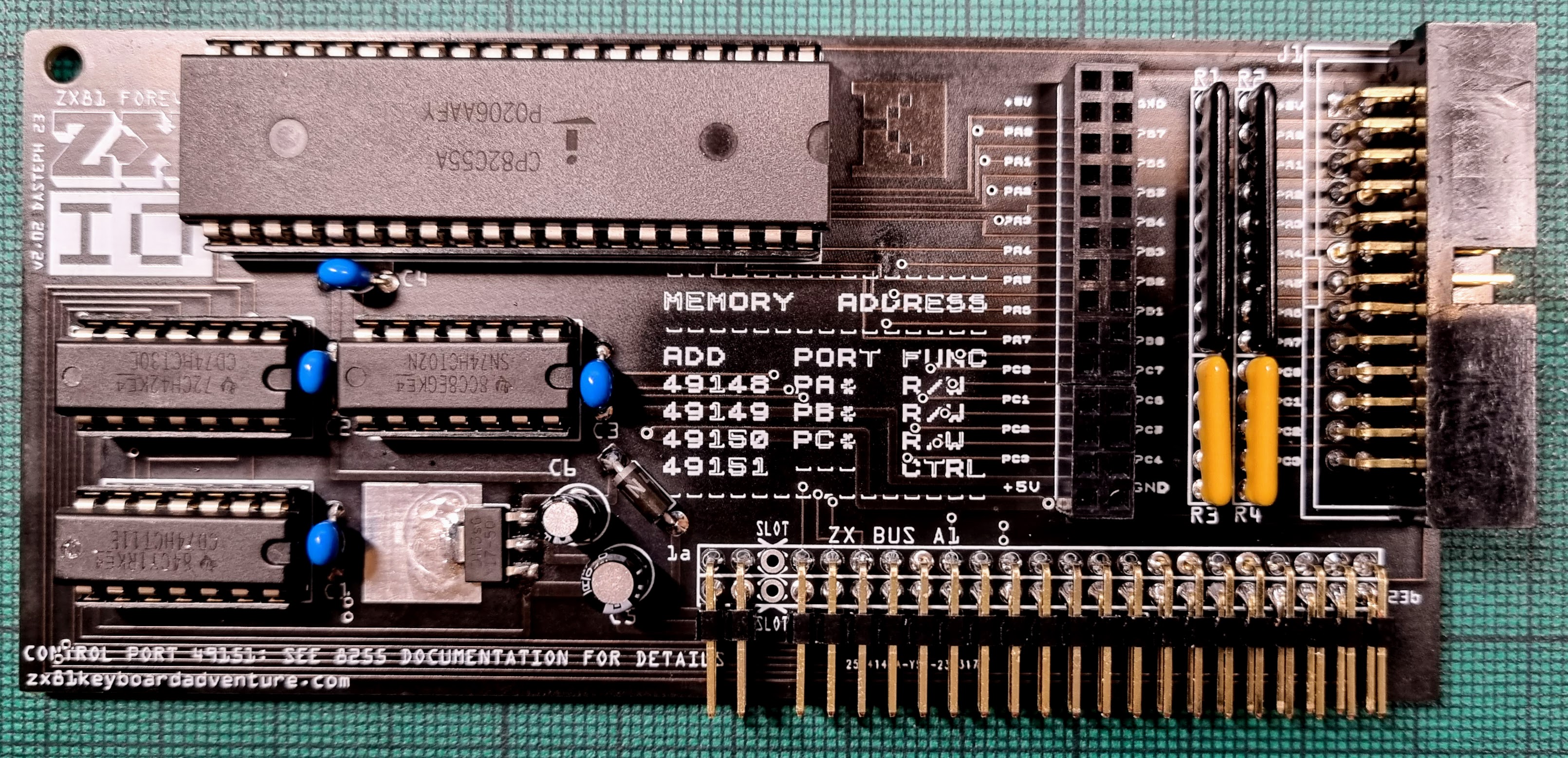
  • Set up the ZXIO V2 / 8255A in Mode 0 for basic I/O.
  • Designate specific ports for communication with the RTC:
    • Port A: Data bus to exchange data with the RTC.
    • Port C: Control lines like chip select (CS),  read/write (R/W), Address Strobe (AS) and Data Strobe (DS).
The DS12C887 is set for Motorola timings, with the MOT pin connected to VCC. The Motorola mode seems to lend itself a little better to being interacted with. 

Interestingly, the Chip Select line on the RTC is active low, as is the Write signal on the R/W lines. I’ve chosen to invert these signals as this seems to make more sense when writing the BASIC program to control the clock. You'll notice on the schematic that I've used a CD74HC02 NOR gate to invert the signals.


As part of the Chip Select inversion, one input of the NOR gate is paired with another output from the CD74HC02, which is connected to ground. This setup creates a small delay, preventing the RTC’s memory from being cleared or reset during power cycles or resets, ensuring it retains its time and configuration data.


RTC for ZXIO V2 Circuit Schematic

A "Functional" Clock Program
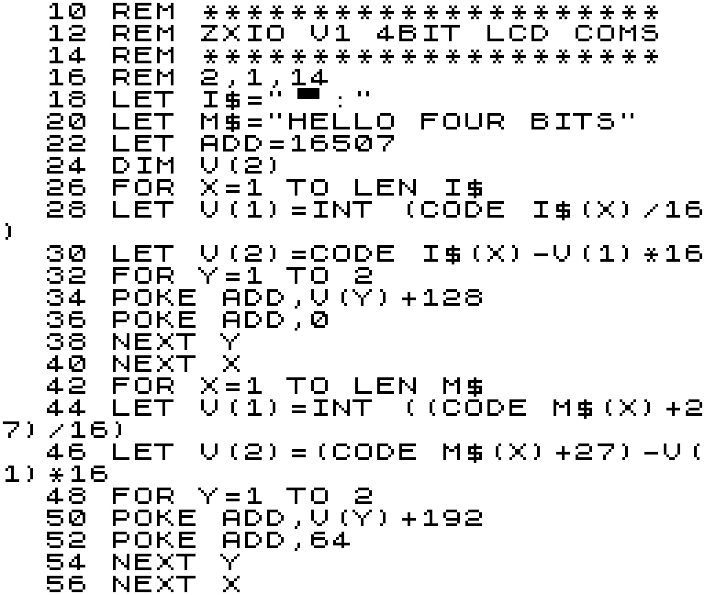
Using the ZXIO V2 interface card, the ZX81 communicates with the RTC by sending and receiving signals through the I/O ports. Each I/O port, along with the Control Port, is memory-mapped to specific addresses on the ZX81. Port A corresponds to memory address 16380, Port B to 16381, Port C to 16382, and the Control Port to 16383. These addresses are used to send commands and data to the RTC. The time data stored in the RTC is in binary-coded decimal (BCD) format, and the program converts this data into a human-readable string for display on the ZX81.

The BASIC program to control all this is divided into two parts, or two separate programs, in reality. The "GET TIME" routine reads hours, minutes, and seconds from the RTC registers, formats them into a string, and displays the current time. The "SET TIME" routine, on the other hand, allows a new time to be programmed into the RTC by converting user-defined input into BCD and writing it back to the appropriate registers.

 
  10 REM **************
  15 REM ** GET TIME **
  20 REM ************** 
  25 LET Y=0
  30 LET A$=""
  35 LET T$=""
  40 FOR X=4 TO 0 STEP -2
  45 POKE 49151,128
  50 POKE 49150,130
  55 POKE 49148,X
  60 POKE 49151,144
  65 POKE 49150,132
  70 LET Y=PEEK 49148
  75 LET A$="0"+STR$ (10*INT (Y/16)+Y-INT (Y/16)*16)
  80 LET Y=LEN A$
  85 LET T$=T$+A$(Y-1 TO Y)+":"
  90 NEXT X
  95 PRINT AT 0,0;T$(1 TO 8)
 100 GOTO 170
 105 REM **************
 110 REM ** SET TIME **
 115 REM ************** 
 120 LET T$="225533"
 125 POKE 49151,128
 130 FOR X=0 TO LEN (T$)-1 STEP 2
 135 LET Y=VAL (T$(X+1 TO X+2))
 140 POKE 49150,130
 145 POKE 49148,LEN (T$)-X-2
 150 POKE 49150,133
 155 POKE 49148,Y-INT (Y/10)*10+INT (Y/10)*16
 160 PRINT Y-INT (Y/10)*10+INT (Y/10)*16,LEN (T$)-X-2
 165 NEXT X
 170 STOP
  

GET TIME (Lines 10–100)

his part retrieves the current time from the RTC module and formats it into a readable string.

  1. Initialisation:

    • Lines 25–35: Variables Y, A$, and T$ are initialised. T$ will hold the final formatted time.
  2. Reading Time Data:

    • Lines 40–90: A loop iterates through the time registers in reverse order (the RTC stores hours, minutes, and seconds in separate registers).
      • Line 45: Writes 128 to the control register to prepare the RTC for a read operation.
      • Line 50: Writes 130 to select the time register.
      • Line 55: Specifies which time register to read (X corresponds to seconds, minutes, or hours).
      • Line 60: Executes the read operation.
      • Line 70: Retrieves the register value using PEEK.
  3. Formatting:

    • Lines 75–85: Converts the binary-coded decimal (BCD) value from the RTC into a two-digit decimal number:
      • Y/16 extracts the tens digit.
      • Y-INT(Y/16)*16 extracts the units digit.
      • The digits are concatenated into A$ and appended to the time string T$ with a colon separator.
  4. Display:

    • Line 95: Displays the formatted time (first 8 characters) at the top-left corner of the ZX81 screen.
  5. Repeat:

    • Line 100: Ends the routine and jumps to the time-setting routine if implemented further.

SET TIME (Lines 105–170)

This part writes a new time into the RTC module.

  1. Initialisation:

    • Line 120: The variable T$ is hardcoded with a new time in the format HHMMSS (e.g., "225533" = 22:55:33).
  2. Writing Time Data:

    • Lines 130–165: A loop iterates through the string T$ in pairs of digits to set the hours, minutes, and seconds registers:
      • Line 135: Extracts two digits from T$ and converts them into an integer.
      • Line 140: Prepares the RTC for a write operation by setting the appropriate control values.
      • Line 145: Specifies the time register to write to.
      • Line 150: Converts the decimal value into BCD format and writes it to the RTC.
  3. Debugging/Confirmation:

    • Line 160: Displays the BCD-encoded value and the register being written to for verification.

Time Loop

With Line 100 changed to "GOTO 35," the "GET TIME" portion of the program becomes a continuously running clock—though it updates slightly slower than real time. The program, as written, takes just under 2 seconds to update. This could be sped up to some degree by only looping through the seconds and minutes as needed, rather than reading the entire time (hours, minutes, and seconds) every time. The video demonstration bellow is taken from slightly earlier version of the program and is slightly slower (slightly).


And that’s a wrap on reading and interacting with the Dallas Real-Time Clock—at least for now. We've successfully coaxed the ZX81 into telling the time (with a slight delay, of course). If we’ve learned anything, it’s that time waits for no one… except maybe for the ZX81, which could probably use a little more time to catch up.


Reference: Dallas RTC DS12C887 Module Pinout

Pin Name Description
1 MOT Motorola Timing Select. Connect to VCC for Motorola timings.
2 X1 Connections for Standard 32.768kHz Quartz Crystal – Internal.
3 X2 Connections for Standard 32.768kHz Quartz Crystal – Internal.
4 D0 Data Bus Line 0 (part of the 8-bit data bus).
5 D1 Data Bus Line 1 (part of the 8-bit data bus).
6 D2 Data Bus Line 2 (part of the 8-bit data bus).
7 D3 Data Bus Line 3 (part of the 8-bit data bus).
8 D4 Data Bus Line 4 (part of the 8-bit data bus).
9 D5 Data Bus Line 5 (part of the 8-bit data bus).
10 D6 Data Bus Line 6 (part of the 8-bit data bus).
11 D7 Data Bus Line 7 (part of the 8-bit data bus).
12 GND Ground.
13 CS~ Chip Select, active low. Selects the RTC for communication.
14 AS Address Strobe. Latches address bits on the falling edge.
15 R/W Read/Write input. Determines whether data is read from or written to the RTC.
16 GND Ground.
17 DS Data Strobe, active low. Enables reading or writing data to the RTC.
18 RESET Reset input, active low. Resets the RTC registers when asserted.
19 IRQ~ Interrupt Request, active low. Signals alarms or periodic events.
20 VBAT Connection for a Primary Battery – Internal.
21 RCLR~ Active-Low RAM Clear. Pin is internally pulled up.
22 NC No Connection (not used).
23 SQW Square Wave output. Outputs a programmable frequency or 1 Hz for timekeeping.
24 VCC Power supply input (typically +5V).


Read More

Sunday, January 07, 2024

ZXIO Interface for the ZX81: Part 6

Leave a Comment


ZX81 ZXIO TalkBot interface and ZXIO Interface
ZXIO-TalkBot and ZXIO V2 (with minor revisions)

ZXIO-TalkBot

Alright, we've got our reliable ZX81 all decked out with the ZXIO V2. Now, let's kick things up a notch - how about introducing an SP0256 (the original retro) speech chip to the party? This little marvel can transform pre-defined sounds (allophones) into speech, bringing a whole new layer of excitement to our setup.


Prior to designing the Talkbot, I made a slight modification to the ZXIO V2 (now V2.1 I guess) board. I introduced a new 4-pin header on the left side of the board, incorporating the NMI, Reset and Clock (foreshadowing)  signals from the ZX81, along with a Gnd line. This addition was made with the anticipation that the extra signals would be beneficial for future expansions. Moreover, the header enhances stability when connecting more extended expansion cards directly to the front of the ZXIO interface.


Of course it's well worth noting that it's quite possible to build an entirely separate / standalone interface board for the SP0256-AL2. When designing the ZXIO-Talkbot, I consulted a number of designs as a reference before planning the ZXIO plugin card. I highly recommend 'How to Make Your Computer Talk' by Steven J. Veltri as an excellent starting point. His book covers interfaces for a number of 80s home computers including the ZX81, along side in depth details on how the SP0256-AL2 itself works.


How to Make Your Computer Talk: T/S 1000, ZX80, and ZX81 Speech Circuit Schematic

The interface circuit from 'How to Make Your Computer Talk' is depicted above. Although as it's designed for Machine Code programs, it is not accessible to BASIC due to the absence of Memory Mapping. However, the fundamental design can be readily adapted for use with the ZXIO expansion card.


In the ZXIO-Talkbot, all addressing and data lines are interconnected with the 8255A on the ZXIO V2 interface card. Consequently, their control is handled in a manner similar to the earlier experiments where we employed the ZXIO V2 to manage an HD44780 LCD board. 


Unlike the 'How to Make Your Computer Talk' board, the clock signal is not produced by a separate 3.12MHz crystal; instead, we utilise the ZX81's own oscillator, which operates at 3.25 MHz—sufficiently close. Additionally, a separate RESET signal is not required; this line is directly connected to the ZX81's RESET. While, in future versions, it could be managed by the 8255A, such a configuration might be considered overkill.


ZXIO TalkBot Schematic, Featuring the SP0256-AL2 Speech Chip


The only other notable difference is the removal of the op-amp. Instead, I've provisioned a 3.5mm headphone jack that's easy enough to connect to powered speakers for all your amplification needs. (Note that there is also a direct connector that goes to my ZonZX-81 sound card.)


Talking the TalkBot

The SP0256 is a speech synthesis chip designed to convert phonetic information into audible speech. It operates by receiving allophone codes, which represent specific variants of a phoneme occurring in particular linguistic contexts. Allophones, unlike phonemes, are concrete variations of sound within a language.


In short, this means that you can't simply give the TalkBot a word and have it 'say' it correctly. Instead, you need to supply it with an allophone list that will hopefully construct a word from its sound samples. Below is a list of allophones, their sound descriptions, and suggested timings that each should be allowed to run.


Unfortunately, the timings are not so useful in ZX81 BASIC, as the instructions take more time to process than desired. Feeding the Talkbot the allophones and ignoring time signatures works sufficiently well. Of course, there's nothing stopping us from addressing the Talkbot/SP0256 later in Assembly for a little more accuracy.


ZXIO SP0256-AL2 Allophones Reference for the ZX81
SP0256-AL2 Allophones Reference

To transmit data to the ZXIO-TalkBot interface we must first configure Port A and Port B on the 8255A IC for output mode. This can be done by POKEing the control register at address 49151 with a value of 128. Once complete, we can begin transmitting control codes. 


The Enable line is first set low on Port B at address 49149, 0, while the allophone control codes are transmitted through Port A at address 49148, 'code'. Then Enable line 1 on port B is set high at 49149, 1. After that, the Enable line is brought low again.


ZXIO-TalkBot and ZXIO V2 interface cards (plus ZX Minstel ZXpand & ZonZX-81)


LCD and TalkBot

The fun doesn't end there; after all, the ZXIO is designed to allow multiple interfaces to be attached simultaneously. As such, we can reuse the LCD interface from the previous project in Part 5, and have it write out what we're asking the ZXIO-TalkBot to say at the same time. For this, we only need to use the upper bits at address 49149 (Port B) to enable and disable its control lines.


ZX81 ZXIO V2 running the LCD and ZXIO-TalkBot Togther Demo 


For your complete audio-visual enjoyment, please play the video below to witness and hear the results. This is just a sample of what could be achieved; the ZXIO V2 Cards and expansions offer almost limitless possibilities. For instance, they could be employed to power a wide array of applications, even extending to interfacing with devices like an Arduino. The potential is expansive, and the video provides just a glimpse of the creative possibilities.


For the moment, that pretty much concludes this mini-series on the ZXIO and ZXIO V2 expansion cards. Further projects based on the board are in the pipeline, and if there's enough interest, I may decide to produce kits and/or complete units. Please let me know if you'd be interested in obtaining a board. If you haven't already, please read over all the related earlier (and future) articles listed below.


See all the other entries for this project:   Part 1Part 2Part 3Part 4Part 5 and Part 6.


Read More

Sunday, May 07, 2023

ZXIO Interface for the ZX81: Part 5

Leave a Comment

IO Boards Comparison, Featuring Hitachi LCDs

Now that we have 2 differing IO boards, why not put them in a side by side comparison. I figured a good test of the board would involve a simple communications project, such as writing out to a character based HD44780 compatible LCD screen.


An HD44780 LCD panel is a character-based liquid crystal display that can display 16 characters per line and up to 2 lines of text. It is widely used in embedded systems and DIY projects because of its low cost, low power consumption, and ease of use. The HD44780 LCD panel is compatible with a wide range of microcontrollers and can be interfaced using a 4-bit or 8-bit command set. We really couldn't ask for a more amiable device for testing ZXIO board differences with.


HD44780 LCD Module Pin out 
Pin
Signal
Function
1VSSGround
2VCC+5 Volts
3VEEContrast adjustment 0V: High Contrast
4RSRegister Select 0: Command, 1:  Data
5R/WRead/Write 0: Write, 1: Read
6ENEnable. Falling edge triggered
7DB0Data Bit 0 (Not used in 4-bit Mode)
8DB1Data Bit 1 (Not used in 4-bit Mode)
9DB2Data Bit 2 (Not used in 4-bit Mode)
10DB3Data Bit 2 (Not used in 4-bit Mode)
11DB4Data Bit 4
12DB5Data Bit 5
13DB6Data Bit 6
14DB7Data Bit 7
15LED A+Anode Back light +  
16LED K-Cathode Back light -

Configuring for the ZXIO V1 Board

Connecting the LCD module to the ZXIO is a straightforward process. The output pins O0 to O3 of ZXIO should be paired with DB4 to DB7 on the LCD board to send data from ZX81 to the module. In addition, the output line 6 of ZXIO must be linked to Register Select, while the output line 7 should be connected to the Enable Pin.

The lines responsible for controlling the power to the LCD module and screen contrast are as follows: VSS is linked to the ground, VCC is linked to +5 volts, and VEE is connected to the ground through a variable resistor (across the +5v line). To adjust the screen brightness, connect the LED+ pin to +5 volts and the LED-pin to the ground through a 220 ohm resistor (resistor is optional as some of these Module clones have the required resistor built in).


ZXIO V1 to LCD Module
That's the hardware out of the way, the rest is all down to some BASIC programming on the ZX81 targeting the ZXIO and LCD display module.

HD44780 LCD Commands (Examples)
Code (HEX)
Code (DEC)
Command to LCD
0x011Clear the display screen
0x022Set to 4 Bit Mode
0x0e14Set Underline Cursor
The below program connects the HD44780 to the ZX81 / ZXIO V1 at address 16507. It initializes the HD44780 by sending a sequence of control codes to set the display mode, enable the display, clear the display, and set the cursor to the home position. To send each byte, it needs to be split into 2 * 4 bits and sent consecutively. The Enable line must be brought high and then low to signal each 4 bit segment sent.

Subsequently, the program transmits the message "HELLO FOUR BITS" to the HD44780 by encoding each character as its corresponding ASCII code. To achieve this, the ZX81 Characters  should to be converted to their ASCII counterparts. As previously mentioned, each byte is then split into two 4-bit segments, with both the Enable and Register Select lines being set high. After transmitting each 4-bit segment, the Enable line is set low once again.

ZX81 Code to drive LCD in 4bit Mode

The program sends data to the LCD screen at a slow but satisfying speed. While this could be accelerated with code optimisation and pre-conversion of the ASCII text, I opted to maintain program similarity between the code directed at the V1 and V2 boards for a more effective side-by-side comparison (see next section).

Output from ZXIO V1 4Bit LCD Program

Configuring for the ZXIO V2 Board

Setting up the V2 interface involves a process similar to that of the V1 version, with the added advantage of utilising the entire 8-bit input lines available on the HD44780 controller board. On the ZXIO V2 board, Port A pins 0 to 7 (facilitated by the 8255A chip) are mapped to the Data pins on the LCD. While, the Register Select and Enable lines are mapped to Port B pins 6 and 7, respectively.

ZXIO V2 to LCD Module

As we're using the full 8-bit input, the configuration commands we need to send to the LCD interface vary slightly as we no longer need to put the device into 4-bit mode. (In both cases we're only using a very small subset of the available command set, just enough to get things moving along.) 


HD44780 LCD Commands (Examples)
Code (HEX)
Code (DEC)
Command to LCD
0x011Clear the display screen
0x0e14Set Underline Cursor
0x3856Set to 8 Bit Mode, Configure Display
To transmit data to the LCD interface using the V2 version, we must first configure Port A and Port B on the 8255A IC for output mode. This can be done by POKEing the control register at address 49151 with a value of 128. Once complete, we can begin transmitting control codes. The Enable line is set high via Port B pin (address 49149), while the control codes are transmitted through Port A (address 49148). After each code, the Enable lines is brought low.

As in the previous version, we first convert our message "HELLO EIGHT BITS" to ASCII before transmitting it to the LCD. We begin by setting the Enable and Register Select lines to high via Port B. Next, we send a character from our message string to Port A, and after transmission, set the Enable line back to low.

ZX81 Code to drive LCD in 8bit Mode

Using the the ZXIO V2 board, our "HELLO" message is send somewhat more speedily, though still managing a rather 80s sci-fi future computer message output speed (All very MU-TH-UR 6000: Look out Ripply!).

Conclusions Drawn??

The discussion above only scratches the surface of the potential applications for both the V1 and V2 ZXIO boards. Despite its simplicity, the LCD test highlights the greater versatility of the V2 board in the long run. Nonetheless, this does not detract from the ease of use of the V1 board. With a simple address change to mend the issues outlined in previous blog posts, the V1 board is an ideal choice for a wide range of hardware experiments.

That being said, the ZXIO V2 design offers more possibilities for exploration due to the presence of the 8255A PIO chip. Future blog posts in this IO series will delve deeper into these possibilities.

Waiting for more in the IO series? Take a read of:  Part 1Part 2Part 3Part 4Part 5 and Part 6.


Read More

Sunday, April 16, 2023

ZXIO Interface for the ZX81: Part 4

Leave a Comment


ZX81 ZXIO V2 Input Output Card with LCD Shield
ZXIO V2 Card with LED Expansion Board

Previously I built a simple Input / Output board for the ZX81, tested it, identified some self induced errors then hinted that it may be worth changing designs completely. Way back in Part 1 I'd already come to the conclusion that I really shouldn't make this a simple project, so of course I went back and stared things again.

Why Change  Now?

Didn't the last design work and only really require some minor addressing changes? Yes, and that would be a perfectly fine end to the IO project. Still I wished to take this further and build a more capable board. Note that the overall aim of building a relatively simple interface is still a primary goal.


The IO version One card has a minor limitation in that it can only support an 8-bit wide addressing, which may not be sufficient for more complex hardware that requires access to at least a partial 16-bit width address space to access control lines while still being able to send and receive 8 bits. There are several ways to address this issue, such as using 4-bit modes or using 7 bits for data and the remaining bit as a control line. However, the feasibility of these solutions depends on the specific interface requirements of the project.


One possible solution is to double the IO options by adding an extra set of latch and buffer ICs. However, this would increase the complexity of building the board, including routing and address decoding. Other options could involve employing a "standard" IO IC.


The 8255A, the IO Chip of Choice (This Time)

Three suitable IO ICs come to mind for our purposes: the Z80-PIO (Parallel Input/Output Interface), the 8255A-PPI (Programmable Peripheral Interface) and the W65C22N-VIA (Versatile Interface Adaptor). All three of these chips are period correct for the ZX81, in production and available of the shelf today (at least in 2023).


For Version 2 of the IO board I selected the 8255A, as it's pretty well documented, and as a bonus it made an appearance in a ZX81 IO board designed by A. Daykin for Maplin's 'Project Book 04' from 1983. With some modifications to the Addressing and IO configurations to make it more suitable for experimentation, the Maplin board can be made pretty well perfect for our needs.


Period Inspiration from Maplin Project Book 04 - 1983
The 8255A IC is a chip that serves as a programmable peripheral interface, allowing for parallel input and output. It has three ports: Port A, Port B, and Port C. Each port can be configured as either an input or an output. Port C can be split into upper and lower blocks, each with the option to be programmed as an input or output. The IC also has a control register that is used to set the mode of operation for each port. With these features, the 8255 IC can replicate and even expand upon all the functions that the first version of the ZXIO board was capable of achieving. It can actually do fair bit more, but we may explore that latter on in this series of posts. 

Maplin IN 

The Maplins design is appropriately simple, making it easy to connect the 8255A to the ZX81. Note that 4 contiguous address locations require mapping, this performed partly by the 8255A and then the supporting ICs. The 8255A chip has two address lines on pins 8 and 9, which are directly linked to the ZX81 address lines Al and AO. The 74 series ICs then handle the remaining address decoding, and enabling of the 8255A when pin 6 is set to logic level 0. All data lines from the ZX81 are directly connected to the 8255A, along with write and read signals. The reset line on the 8255A at pin 36 is tied to GND.


The 16 IO pins of the 8255A that make up Ports A and C are directly connected to pin headers at the edge of the Maplin board for external device connection. However, the pins of Port B are linked to IC5 and IC6, which buffer the outputs from the 8255A. In conjunction with a set of 4.7k resistors, this setup offers protection against overload. The purpose of this configuration is to drive potentially higher voltage equipment from Port B. A side affect of the buffering is to limit Port B to output only.


Each IO Port and a Control Port are Memory Address Decoded back to the ZX81, Specifically, Port A corresponds to memory address 16380, Port B corresponds to memory address 16381, Port C corresponds to memory address 16382, and the Control Port corresponds to memory address 16383. These addresses are located at the top of ZX81s 8 to 16k range where a copy of the ROM would normally be shadow mapped. Refer back to Part 2 in this series for details on address ranges and suggested uses.


** For additional details on the Maplin Board I'd recommend Allan Faulds blog page, where he builds up an original Maplin IO Board purchased in the 1980's. **


ZXIO V2 OUT

Although there aren't many modifications needed to transform the Maplin into a ZXIO V2, there are a few adjustments I would like to implement to enhance the design's practicality for contemporary experimentation.


The initial modification I made was to adjust the address mapping to span from 49148 to 49151. This will position the device at the upper end of the 40-48k memory segment, beyond the reach of numerous contemporary and historic memory expansion cards (not all, but many). 


I eliminated the buffering ICs from Port B, if buffering becomes necessary, we can always incorporate that back into external hardware. I also took the opportunity to ground output lines on Ports A to C via 4.7k resistors, this will prevent floating values on the lines when they're not connected to anything. Additionally the Reset line on the 8255A is now tied to the Z80 / ZX81's reset signal, inverted through spare NAND gates from the address decoding ICs.


ZXIO V2 Schematic.

The last functional modification consists of two headers. The first one is an IDC header resembling the ZXIO version 1 board, which includes the IO Lines, Ports A to C, Ground, and +5 Volts. This facilitates the use of IDC cables to connect to external breadboards or built-up external devices. Additionally, I added a female header in parallel, allowing for direct connection to plug-in boards, like the LED "hat" shown in the photo at the top of this post.


ZXIO V2 Test Board

Next Post?

This should mostly cover the essential hardware details of ZXIO V2. In my next blog entry, I plan to conduct a quick comparison between the old and new ZXIO boards. Although I am confident that V2 is a more versatile board, V1 remains a decent option for basic experimentation. Lets see, stay tuned for the next post.

Until then see all the other entries for this project:   Part 1Part 2Part 3Part 4Part 5 and Part 6.


Read More

Friday, March 03, 2023

ZXIO Interface for the ZX81: Part 3

Leave a Comment

Testing ZXIO Boards with a Variety of ZX81 and Minstrel Hardware Options
We're finally at the point where I go over the actual test ZXIO boards, test the addressing changes and learn why I mentioned in the first article that memory address 16507 is the "perfect location for an Output Board, and an interesting, possibly flawed location for an Input Board"

Boards as Envisaged?

After some simple initial testing I had prototype ZXIO boards produced. The core board along with breadboard friendly breakout boards, these components are designed to connect via a 20 pin IDC cable for easy IO experimentation. This arrangement also made testing the boards a relatively simple process.

While building the device I'd noticed I'd not connected the +9v power rail to the voltage rectifier, which needed fixing with some bodge wire. Somehow I'd left the line off on the schematic. I caught this issue out after noticing some odd voltage drops on the input / output lines. Interestingly the whole board was being powered by vampire voltages sourced from the ZX81's Address lines up until this point. 

ZXIO Test Board with Accessories

With power problems sorted, testing the Output lines was a simple matter of POKE-ing address 16507,  data lines checked individually with their corresponding decimal value, 1,2,4,8,16,32,64 and 128. This test checked out fine. The next step, writing a  up a 'traditional' counting application cycling for 0 to 255, POKE-ing the  numbers and watching the LED's flash accordingly. A delightfully flash result was produced.

Input testing was a not to dissimilar process, only in reverse. With the breakout PCB mounted on a breadboard, I tested each input with a 220 ohm  resistor from +5v (included in the breakout pins) routed to each of the input data lines in turn. The ZX81 was set to PEEK at address 16507 and each of the lines read back correctly. All good so far.

Last major test was to cycle values through the Output and Inputs at the same time. If everything was working as expected I should be getting different values in to what I was sending out. If I was POKE-ing 255 out and had the inputs setup for say 15, I should see 255 on the LED display (which is output only), but be getting a value of 15 when conducting a read / PEEK-ing at address 16507.

This was also all good on my initial testing as conducted using a ZX Minstrel Issue 3 (Tynemouth Software's ZX81 Clone) with the its ZXpand attached. Then I moved the experiments over to a real ZX81 and things were not quite as rosy there.

Tales of RAM Packs and Modern Expansions

ZX81 and ZX Minstrel 3 Expansion Options

Over on a 'real' ZX81 with a period correct 16k RAM pack, attempting to write out and read in would produce an accumulation, for example if POKE-ing out 1 and setting up the input lines to be 2, you end up with a value of 3, Essentially the combination of bits. So what's going on, why the difference? In hindsight I really should have expected the results I'm getting from the ZX81, but to understand why we'll need to look at how memory packs work on the 81.

To use external ZX81 RAM packs, the internal 1k RAM of the machine must be disabled first. This can be done by raising the RAMCS line on the expansion bus to +5v. Once a 16k expansion is added, the memory map will follow the layout as described in Part 2, with the additional 16k of memory appearing between addresses 16384 and 32767. l was expected when laying out the idea of the ZXIO and placing our memory mapping at address 16507 in an unused location in the system variable table. What I hadn't calculated for was the inability to disable the external RAM in a similar fashion.

ZXIO Schematic for 16507 Addressing as Tested. (Note RAMCS mostly, wouldn't recommend building)

It appears that both the Minstrel and modern RAM expansions for the ZX81, such as the ZXpand+, are keeping a watch on the ROMCS and RAMCS lines for any other activity. The purpose of this is would be to enable the functioning of any devices that utilise memory mapping and that may be mapped to areas occupied by the additional 32k of memory provided by these modern expansions.

Older period memory packs are not functioning in the same manor. Most if not all would be anticipating memory mapped devices to be located in the ROM mirror areas. To this end all my setting RAMCS to high is doing is affirming that yes the ZX81 should be using external RAM.

This is precisely what I meant earlier when I suggesting that memory address 16507 would be the ideal location for an Output Board. It is an area of RAM that is otherwise not utilised, making it perfect for setting up external devices to read from. However, if old RAM pack hardware is connected and data is written back to this address, it is likely to result in confusion at the bit or byte level.

So that's where we're at for the moment, we have an IO board that works perfectly with modern ZX81 hardware, not so much with period pieces. Next step I'm guessing is to move the memory mapping to somewhere the shadow ROMS are expected to be. Much like the original design from ETI Canada only a little more targeted like we tried out this time around. It might also be tempting to try out another design of IO board entirely, but all this is for the next set of posts in the series.

Until then see all the other entries for this project:   Part 1Part 2Part 3Part 4Part 5 and Part 6.


Read More

Sunday, February 19, 2023

ZXIO Interface for the ZX81: Part 2

Leave a Comment


Last post I mentioned that the ZXIO add-on is memory mapped to location 16507. So this time I go over why 16507 and dig into Memory Mapping at little.

Let's Talk about Memory Mapping

The main problem with mapping an IO device to a memory location is that it can remove that location from the ZX81's physical memory. Meaning that you can potentially poke black holes right into a location crucial for executing your applications. Not so good but avoidable.

To understand where to locate a memory mapped device let's first cover the basics: The first 8k is always devoted to ROM, the second 8k is by default is a shadow copy of ROM. This is then followed by a block of RAM either a 1k block followed subsequently by 16 shadow 1k copies of the first on a stock machine; or on a 16k expanded ZX81, an entire 16k block. In both a 1k and 16k machines, RAM addressing tops out at address 32767. Then we find 2 shadow copies of ROM taking up a 16k slot and finally shadow copies of RAM identical to those located between addresses 16384 and 32767.

ZX81 Memory Map in Standard 16k and an Example 32k Configuration

Block

Add Dec

Add Hex

16K RAM Map

32K ZXpand (Low Map)

0 - 8k

00000-08191

0000-1FFF

ROM

ROM

8 - 16k

08192-16383

2000-3FFF

ROM (Copy 0000-08191)

RAM

16 - 24k

16384-20479

4000-4FFF

RAM

RAM

24- 32k

20480-32767

6000-7FFF

RAM

RAM

32 - 40k

32768-40959

8000-9FFF

ROM (Copy 0000-08191)

RAM

40 - 48k

40960-49151

A000-BFFF

ROM (Copy 0000-08191)

ROM (Copy 0000-08191)

48 - 56k

49152-57343

C000-DFFF

RAM (Copy 4000-4FFF)

RAM (During M1)

56 - 64k

57344-65535

E000-FFFF

RAM (Copy 6000-7FFF)

RAM (During M1)


That's the basic 1k to 16k out of the way. If we have more memory the map changes. Each of the shadow copies of ROM can be switched out to accommodate extra RAM in 8k blocks (I'll post-fix that statement with normally). For example a 32k machine might switch out the first and second copies of the ROM located at 2000 to 3FFF and 8000 and 9FFF. This would give the ZX81 32k of contiguous RAM to play with. However it's worth noting that BASIC programs can only be located within a 16k area between 16384 and 32767, exactly the same 16k area as in the original memory map. That's not to say that the extra RAM is inaccessible to BASIC, you can PEEK and POKE the entire memory configuration. This ability is fortunate as memory mapping additional hardware requires this same functionality.

Memory Mapping Hardware Devices (Somewhere)

Much like swapping in RAM, add-ons can assume the memory location designated for shadow ROM, additionally we can claim areas of RAM. All well a good but where would we want to locate our devices in the memory map. This of course is not a new discussion, Nick Lambert of Quicksilva proposed a Memory Map standard for Peripherals all the way back in 1982, where he lays out where exactly he feels certain types of peripherals should live.

The below table is taken from SQ Quarterly Issue Volume 1, Issue 1, where you'll find quite an extensive article on the ZX80 & 81's Memory Maps, well worth reading, and it covers quite some ground that I won't go into here.

Nick Lambert of Quicksilva's Proposed Memory Map for Peripherals (SQ Quarterly 1-1 1982) 

Of course Nick's standard probably saw very little traction, and by the time anybody cared enough to follow a 'standard' they'd most likely moved onto squabbling around similar issues with the ZX Spectrum. Regardless, he does highlight the 2 most common areas where manufacturers and purveyors of DIY kits would naturally choose to locate their add-ons, the shadow ROM areas.

Now as mentioned in Part 1, in order to save wads of cash, address mapping was normally keep to a minimum, with large areas mapped to reduce IC counts. Now of course if you're playing around with a ZX81 you're going to want to maximise your RAM (just because you can, plus there really are applications the use it all), and all that RAM is already likely to be occupying the shadow ROM areas. This of course pretty much rules out every location (exaggerating a bit for effect). In reality we can get very specific on addressing, right down to the byte, a good scheme might be to map to the upmost ROM/RAM area unused by BASIC, say 16383. But if we're going to get that specific there is another creative option open to us.

16507 and Friends

The bytes in memory, 16384 to 16508 hold the ZX81 System Variables. Of the 124 bytes set aside for System Variables, there are 3 listed as not used in the ZX81 BASIC Programming Manual. (Why is this? Steven Vickers might know, personally, I haven't a clue) These unused bytes are 16417, 16507 and 16508, they are perfect for our purposes.

The major catch with mapping a peripheral into the unused System Variables space is that any programmer looking to claw free space (particularly those building 1k apps) is going to hunt these down and use them. Doing so will prevent our prospective IO device and such memory scrounging programs from running correctly. As with pretty much all memory mapping issues, this is easily solved by removing the offending device. Still it's both worth both pointing out and remembering in those cases where something odd happens, say when running that special copy of "1k Monkey Clown Car Mega Racer Game TM".

In Theory

For the first iterations of the ZXIO board I've chosen address 16507 as it affords the opportunity in latter revisions in claiming 16508, giving 2 adjoining addresses and some really interesting possibilities. Of course this is well into the future, first priorities are / were getting the initial prototype up and running.

Next Up  

We'll get onto designing and building the ZXIO, plus issues and I encountered along the way. Pretty much what you'd expect from a write up. 

See all the other entries for this project:   Part 1Part 2Part 3Part 4Part 5 and Part 6.


Read More

Tuesday, February 14, 2023

ZXIO Interface for the ZX81: Part 1

Leave a Comment

Testing a Prototype ZXIO interface

This is the first in a new series of articles where I explore building an Input / Output board for the ZX81 (and clones), where I start with the idea of keeping it simple and probably fail at the simple part. 

Didn't You Already Make an IO Board?

Um, yes, yes I did, way back in 2018 I Build an IO board based on the a design found in the book Easy Add-On Projects for the Spectrum, ZX81 & Ace, this worked as intended and fun was had. Having used the Add-On Projects board for a while, I came to the conclusion that it was a overly complicated to engage with as a platform for experimentation. This applies physical and when paired with a ZX81 digitally. 

The Add-On Projects board has plenty of input/output pins, but I find them to be arranged in a slightly non-intuitive way, one that makes it difficult to expand / breakout from. That's my fault to an extent, the original design has the use of crocodile clips in mind, when I made my version I tailored towards dupont connections, dupont wires will only stretch so far from the computer. Still, I kept the layout and that's sub-optimal from today's perspective where we're used to breakout boards, hats and shields and the like for extended tinkering. 

The other main issue I have with the Add-On Projects board is that it's I/O Port mapped, meaning you can't access the device natively in ZX81 BASIC and must load a Binary program to access the hardware. Again, this is not a real obstacle, more of an annoyance, a limiting factor. A better approach (for BASIC use) is to memory map an IO board.  It's worth noting that that's a ZX81 problem, if using the Add-On Projects board with a ZX Spectrum you can query any available port.

What do I Want in a ZX81 IO Board?

The main thing I'm after on a new IO board is simplicity; easy to build, easy to connect and interface with, and accessible from BASIC.  All in all a not to complicated shopping list. To make this happen I could modify the Add-On Projects schematic, but since I'm looking at building something new, why not take some other examples out there as inspiration.


So it was off to the various fantastic archive sites for some research. Emerging some time latter, having trawled through period books and many a magazines, I found pretty much exactly what I was after in ETI Canada, Issue April 1983. There presented within the dusty digital pages a perfectly simple IO board. Interestingly once again it's a board designed for both the ZX81 and the ZX Spectrum. This time though there was an option to map it to Memory Addresses rather than ports. 


ZX IO Interface as published in the April 1983 Edition of ETI Canada

Of course just about any device can be mapped to a memory address, I guess the main reason this interface sticks out is because it implicitly does so and that the IO meat of the circuit is a simple as simple can be. To directly quote the original article in ETI:

"The eight board outputs are via PL1 and PL2 from the outputs of the 8-bit latch, IC1. The eight inputs to IC1 are connected to the ZX data bus lines DO -D7, so that when IC3b pin 6 pulses low the data present on DO-D7 is clocked into the latches. It will be held there until another ZX 'write' operation, to a suitable memory or I/O address, updates it.

IC2 contains 8 'tri-state' buffers. The inputs to these buffers are connected to the I/O board input points on PL3 and PL4. The output of each buffer is connected to one of the ZX data bus lines, but normally has no effect because the IC2 outputs are held open-circuit by a 'high' input to pins 1 and 19. When, however, the ZX does a 'read' operation from a suitable memory or I/O address, so that pin 3 of IC3a goes low, the output circuits of the buffers are enabled, transferring the information present at IC2 inputs to the ZX data bus lines."

In a nutshell IC1 and IC2 are handling the input / output, the remaining IC's are performing the address decoding, read and write detecting and ROM disabling. All pretty clear from the circuit diagram (and explanation in the article, which you should read).


Now about that memory mapping, The ETI IO board is mapped to 'All' addresses between 8192 and 16383 (8192 to 16383), that's an entire 8k Area, one normally reserved on a stock ZX81 as a ROM mirror. This broad approach in address mapping is quite normal, as is knocking out the ROM mirror and a good way to reduce costs by keeping IC costs / counts low. But cost is not a factor these days, so for my prototype IO board I decided I'd rather map an individual address, and made the necessary changes to the schematic (among some other minor changes). I chose address 16507.


Now 16507 is actually an unused address in the System Variable table. A very convenient free space, perfect for locating an IO board right?  Of course nothing comes for free, still short answer is yes it makes the perfect locations for an Output Board, and an interesting, possibly flawed location for an Input Board. 


The Board Worked... But.. Next Time?

Bit of a cliff hanger and no real explanation, and a rather sudden slightly disjointed end to Part 1. Next time I'll get into some details about the prototype and why I'm a fair way from done with this 'Simple' project. I did mention I wanted a simple project at the beginning of the article right? Seems I lied to myself.


See all the other entries for this project:   Part 1Part 2Part 3Part 4Part 5 and Part 6.


Read More