Showing posts with label Hitachi LCD. Show all posts

Sunday, January 07, 2024

ZXIO Interface for the ZX81: Part 6

Leave a Comment


ZX81 ZXIO TalkBot interface and ZXIO Interface
ZXIO-TalkBot and ZXIO V2 (with minor revisions)

ZXIO-TalkBot

Alright, we've got our reliable ZX81 all decked out with the ZXIO V2. Now, let's kick things up a notch - how about introducing an SP0256 (the original retro) speech chip to the party? This little marvel can transform pre-defined sounds (allophones) into speech, bringing a whole new layer of excitement to our setup.


Prior to designing the Talkbot, I made a slight modification to the ZXIO V2 (now V2.1 I guess) board. I introduced a new 4-pin header on the left side of the board, incorporating the NMI, Reset and Clock (foreshadowing)  signals from the ZX81, along with a Gnd line. This addition was made with the anticipation that the extra signals would be beneficial for future expansions. Moreover, the header enhances stability when connecting more extended expansion cards directly to the front of the ZXIO interface.


Of course it's well worth noting that it's quite possible to build an entirely separate / standalone interface board for the SP0256-AL2. When designing the ZXIO-Talkbot, I consulted a number of designs as a reference before planning the ZXIO plugin card. I highly recommend 'How to Make Your Computer Talk' by Steven J. Veltri as an excellent starting point. His book covers interfaces for a number of 80s home computers including the ZX81, along side in depth details on how the SP0256-AL2 itself works.


How to Make Your Computer Talk: T/S 1000, ZX80, and ZX81 Speech Circuit Schematic

The interface circuit from 'How to Make Your Computer Talk' is depicted above. Although as it's designed for Machine Code programs, it is not accessible to BASIC due to the absence of Memory Mapping. However, the fundamental design can be readily adapted for use with the ZXIO expansion card.


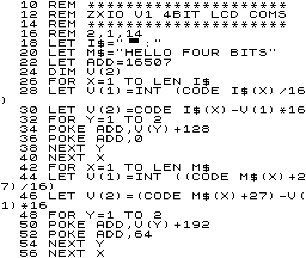
In the ZXIO-Talkbot, all addressing and data lines are interconnected with the 8255A on the ZXIO V2 interface card. Consequently, their control is handled in a manner similar to the earlier experiments where we employed the ZXIO V2 to manage an HD44780 LCD board. 


Unlike the 'How to Make Your Computer Talk' board, the clock signal is not produced by a separate 3.12MHz crystal; instead, we utilise the ZX81's own oscillator, which operates at 3.25 MHz—sufficiently close. Additionally, a separate RESET signal is not required; this line is directly connected to the ZX81's RESET. While, in future versions, it could be managed by the 8255A, such a configuration might be considered overkill.


ZXIO TalkBot Schematic, Featuring the SP0256-AL2 Speech Chip


The only other notable difference is the removal of the op-amp. Instead, I've provisioned a 3.5mm headphone jack that's easy enough to connect to powered speakers for all your amplification needs. (Note that there is also a direct connector that goes to my ZonZX-81 sound card.)


Talking the TalkBot

The SP0256 is a speech synthesis chip designed to convert phonetic information into audible speech. It operates by receiving allophone codes, which represent specific variants of a phoneme occurring in particular linguistic contexts. Allophones, unlike phonemes, are concrete variations of sound within a language.


In short, this means that you can't simply give the TalkBot a word and have it 'say' it correctly. Instead, you need to supply it with an allophone list that will hopefully construct a word from its sound samples. Below is a list of allophones, their sound descriptions, and suggested timings that each should be allowed to run.


Unfortunately, the timings are not so useful in ZX81 BASIC, as the instructions take more time to process than desired. Feeding the Talkbot the allophones and ignoring time signatures works sufficiently well. Of course, there's nothing stopping us from addressing the Talkbot/SP0256 later in Assembly for a little more accuracy.


ZXIO SP0256-AL2 Allophones Reference for the ZX81
SP0256-AL2 Allophones Reference

To transmit data to the ZXIO-TalkBot interface we must first configure Port A and Port B on the 8255A IC for output mode. This can be done by POKEing the control register at address 49151 with a value of 128. Once complete, we can begin transmitting control codes. 


The Enable line is first set low on Port B at address 49149, 0, while the allophone control codes are transmitted through Port A at address 49148, 'code'. Then Enable line 1 on port B is set high at 49149, 1. After that, the Enable line is brought low again.


ZXIO-TalkBot and ZXIO V2 interface cards (plus ZX Minstel ZXpand & ZonZX-81)


LCD and TalkBot

The fun doesn't end there; after all, the ZXIO is designed to allow multiple interfaces to be attached simultaneously. As such, we can reuse the LCD interface from the previous project in Part 5, and have it write out what we're asking the ZXIO-TalkBot to say at the same time. For this, we only need to use the upper bits at address 49149 (Port B) to enable and disable its control lines.


ZX81 ZXIO V2 running the LCD and ZXIO-TalkBot Togther Demo 


For your complete audio-visual enjoyment, please play the video below to witness and hear the results. This is just a sample of what could be achieved; the ZXIO V2 Cards and expansions offer almost limitless possibilities. For instance, they could be employed to power a wide array of applications, even extending to interfacing with devices like an Arduino. The potential is expansive, and the video provides just a glimpse of the creative possibilities.


For the moment, that pretty much concludes this mini-series on the ZXIO and ZXIO V2 expansion cards. Further projects based on the board are in the pipeline, and if there's enough interest, I may decide to produce kits and/or complete units. Please let me know if you'd be interested in obtaining a board. If you haven't already, please read over all the related earlier (and future) articles listed below.


See all the other entries for this project:   Part 1Part 2Part 3Part 4Part 5 and Part 6.


Read More

Sunday, May 07, 2023

ZXIO Interface for the ZX81: Part 5

Leave a Comment

IO Boards Comparison, Featuring Hitachi LCDs

Now that we have 2 differing IO boards, why not put them in a side by side comparison. I figured a good test of the board would involve a simple communications project, such as writing out to a character based HD44780 compatible LCD screen.


An HD44780 LCD panel is a character-based liquid crystal display that can display 16 characters per line and up to 2 lines of text. It is widely used in embedded systems and DIY projects because of its low cost, low power consumption, and ease of use. The HD44780 LCD panel is compatible with a wide range of microcontrollers and can be interfaced using a 4-bit or 8-bit command set. We really couldn't ask for a more amiable device for testing ZXIO board differences with.


HD44780 LCD Module Pin out 
Pin
Signal
Function
1VSSGround
2VCC+5 Volts
3VEEContrast adjustment 0V: High Contrast
4RSRegister Select 0: Command, 1:  Data
5R/WRead/Write 0: Write, 1: Read
6ENEnable. Falling edge triggered
7DB0Data Bit 0 (Not used in 4-bit Mode)
8DB1Data Bit 1 (Not used in 4-bit Mode)
9DB2Data Bit 2 (Not used in 4-bit Mode)
10DB3Data Bit 2 (Not used in 4-bit Mode)
11DB4Data Bit 4
12DB5Data Bit 5
13DB6Data Bit 6
14DB7Data Bit 7
15LED A+Anode Back light +  
16LED K-Cathode Back light -

Configuring for the ZXIO V1 Board

Connecting the LCD module to the ZXIO is a straightforward process. The output pins O0 to O3 of ZXIO should be paired with DB4 to DB7 on the LCD board to send data from ZX81 to the module. In addition, the output line 6 of ZXIO must be linked to Register Select, while the output line 7 should be connected to the Enable Pin.

The lines responsible for controlling the power to the LCD module and screen contrast are as follows: VSS is linked to the ground, VCC is linked to +5 volts, and VEE is connected to the ground through a variable resistor (across the +5v line). To adjust the screen brightness, connect the LED+ pin to +5 volts and the LED-pin to the ground through a 220 ohm resistor (resistor is optional as some of these Module clones have the required resistor built in).


ZXIO V1 to LCD Module
That's the hardware out of the way, the rest is all down to some BASIC programming on the ZX81 targeting the ZXIO and LCD display module.

HD44780 LCD Commands (Examples)
Code (HEX)
Code (DEC)
Command to LCD
0x011Clear the display screen
0x022Set to 4 Bit Mode
0x0e14Set Underline Cursor
The below program connects the HD44780 to the ZX81 / ZXIO V1 at address 16507. It initializes the HD44780 by sending a sequence of control codes to set the display mode, enable the display, clear the display, and set the cursor to the home position. To send each byte, it needs to be split into 2 * 4 bits and sent consecutively. The Enable line must be brought high and then low to signal each 4 bit segment sent.

Subsequently, the program transmits the message "HELLO FOUR BITS" to the HD44780 by encoding each character as its corresponding ASCII code. To achieve this, the ZX81 Characters  should to be converted to their ASCII counterparts. As previously mentioned, each byte is then split into two 4-bit segments, with both the Enable and Register Select lines being set high. After transmitting each 4-bit segment, the Enable line is set low once again.

ZX81 Code to drive LCD in 4bit Mode

The program sends data to the LCD screen at a slow but satisfying speed. While this could be accelerated with code optimisation and pre-conversion of the ASCII text, I opted to maintain program similarity between the code directed at the V1 and V2 boards for a more effective side-by-side comparison (see next section).

Output from ZXIO V1 4Bit LCD Program

Configuring for the ZXIO V2 Board

Setting up the V2 interface involves a process similar to that of the V1 version, with the added advantage of utilising the entire 8-bit input lines available on the HD44780 controller board. On the ZXIO V2 board, Port A pins 0 to 7 (facilitated by the 8255A chip) are mapped to the Data pins on the LCD. While, the Register Select and Enable lines are mapped to Port B pins 6 and 7, respectively.

ZXIO V2 to LCD Module

As we're using the full 8-bit input, the configuration commands we need to send to the LCD interface vary slightly as we no longer need to put the device into 4-bit mode. (In both cases we're only using a very small subset of the available command set, just enough to get things moving along.) 


HD44780 LCD Commands (Examples)
Code (HEX)
Code (DEC)
Command to LCD
0x011Clear the display screen
0x0e14Set Underline Cursor
0x3856Set to 8 Bit Mode, Configure Display
To transmit data to the LCD interface using the V2 version, we must first configure Port A and Port B on the 8255A IC for output mode. This can be done by POKEing the control register at address 49151 with a value of 128. Once complete, we can begin transmitting control codes. The Enable line is set high via Port B pin (address 49149), while the control codes are transmitted through Port A (address 49148). After each code, the Enable lines is brought low.

As in the previous version, we first convert our message "HELLO EIGHT BITS" to ASCII before transmitting it to the LCD. We begin by setting the Enable and Register Select lines to high via Port B. Next, we send a character from our message string to Port A, and after transmission, set the Enable line back to low.

ZX81 Code to drive LCD in 8bit Mode

Using the the ZXIO V2 board, our "HELLO" message is send somewhat more speedily, though still managing a rather 80s sci-fi future computer message output speed (All very MU-TH-UR 6000: Look out Ripply!).

Conclusions Drawn??

The discussion above only scratches the surface of the potential applications for both the V1 and V2 ZXIO boards. Despite its simplicity, the LCD test highlights the greater versatility of the V2 board in the long run. Nonetheless, this does not detract from the ease of use of the V1 board. With a simple address change to mend the issues outlined in previous blog posts, the V1 board is an ideal choice for a wide range of hardware experiments.

That being said, the ZXIO V2 design offers more possibilities for exploration due to the presence of the 8255A PIO chip. Future blog posts in this IO series will delve deeper into these possibilities.

Waiting for more in the IO series? Take a read of:  Part 1Part 2Part 3Part 4Part 5 and Part 6.


Read More