Sunday, February 19, 2017

Lode Runner on the ZX81 - Part 2 (Level Design)

Leave a Comment
There are going to be numerous challenges facing the design and implementation of Lode Runner on the ZX81, and one of the first I need to consider is level storage.

The original Apple II version of Lode Runner comprised 150 levels, these were loaded from disk when required. The ZX81 doesn't afford us the luxury of being able to load from a disk or tape without clearing the running application and memory. So even if we assume our ZX81 has 32k of RAM (about the maximum for the time), squeezing all 150 levels into the diminutive black box is an insurmountable task.

There are modern storage solutions available such as the ZXpand, that could be used to negate the space restrictions, however there is no common file access method shared across these modern deceives. So regardless of current available solutions, the challenge here is to fit as many levels as possible into the resources we do have at our disposal.

To make the challenge slightly easier I'm going to base the level design on the Apple II version, not the (possibly expected) ZX Spectrum incarnation. The reason for this is a simple matter of level storage space. The Apple II maps are a convenient space saving 28 wide x 16 tiles high, where as the Spectrum versions comes in at 32 wide x 22 tiles high. Or to put it another way, 448 tiles on the Apple version versus 704 tiles on the Spectrum version per level to define.

If we look to any "type in" game from the period as a (bad) example, most defined entire screens in the program listings on a one to one tile basis. This method would uses 1 byte per tile, and clearly there is not enough space in a ZX81 for even 10 levels defined in this manner (and still have a game to play). It's imperative to compress each level down as far as possible.

The solution is to store the tile type and the number of tiles(of the same type)  in succession into 1 byte. To achieve this, we can use two 4 bit numbers. This affords us up to 16 available tile types, and 16 successions of that tile. Wwe add the number of tile repeats, 0 to 15 to the tile type value. The tile type value is bit shifted before the addition, and this will produce an 8bit number we can store.


Lode Runner Map Tiles: 4 bit Number Values Chart
Tile No4 Bit ShiftedLevel Starting Position Tile Type
000000Empty: Clear Tile / Background
001016Block: Can't dig through tile
002032Bricks: Can be dug into to create traps
003048Bricks, Fake: Player falls through fake bricks
004064Rope: Player can move horizontally, or jump down
005080Ladder: Visible all game / level
006096Ladder, Escape: Visible only after all gold is collected on a level
007112Gold: Player to collect all gold
008128Guard: Starting position of Guards. After level begins guards fall from the top of screen (after being trapped).
009144Player: The Lode Runner


For example, using the table above, if we require 4 Bircks in a row, we take the value of Bricks, 32 and add it to the number of required repeats 3, for a total of 35. In, in order to produce the entire starting positions of the first level of the Apple II version of Load Runner, each of the 16 rows would be defined as bellow.

01) 15,1,96,8,
02) 3,112,12,96,8,
03) 38,80,38,2,96,8,
04) 6,80,73,96,3,112,3,
05) 6,80,3,33,80,2,38,80,33,
06) 6,80,3,33,80,9,80,1,
07) 4,128,0,80,3,33,80,9,80,1, (missing right guard and gold)
08) 33,80,36,3,39,80,38,
09) 1,80,15,0,80,6,
10) 1,80,10,128,4,80,6,
11) 40,80,41,80,6,
12) 8,80,9,80,6,
13) 6,112,0,80,73,80,2,112,2,
14) 3,80,37,8,38,80,
15) 3,80,8,144,1,112,8,80,
16) 47,43


Lode Runner, Level 1, Apple II Version

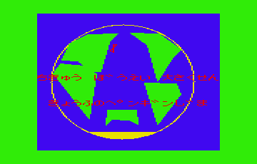
After reading the level data as outlined, the ZX81 level would look something like the bellow screen shot (if using standard character set, no hires graphics yet). Notice that the the escape ladder is drawn in with the "S" character.

Lode Runner, Level 1, ZX81 level Map., Starting Position.


Rather than guess the levels layout, I converted directly from the LodeRunner TotalRecall levels, as (re-)implented by Simon Hung. The TotalRecall levels are implemented in ASCII, which makes reading them easy. The ZX81 map is missing the 2nd guard and gold on line 7, I overlooked these items when writting up the test.

That's all for now, be assured I'm still wotking away on the project, it's just going a little slower than anticipated due to some time and life constraints.
Read More

Tuesday, February 14, 2017

Advancing along with the Retrofitting of a ZX81

Leave a Comment
At the end of the last article, 'Simple Start To Retrofitting A ZX81', a new power supply was sourced and a composite video mod was fitted. This entry sees the near completion of the internal retrofitting project; where some capacitors are replaced, a new voltage regulator is fitted, a lower Amperage CPU inserted and some heatsinks affixed.

Replace Those Old Capacitors


Over a number of years, particularly if exposed to continual high temperatures, electrolytic capacitors tend towards failure. While there is no obvious evidence that the capacitors in my ZX81 have bitten the dust, they are 35 old and probably due for replacement even if purely as a precautionary measure.

Depending on the Issue number of a ZX81, there will be either 2 or 3 electrolytic capacitors on the main board. I have an Issue 1 USA board, as such there are 2 capacitors I'd be replacing. The caps are numbered C3 and C5, are located up the back of the ZX81 PCB, to the right of the modulator and left of the expansion edge.

New Capacitors in Place
Visually the 35 year old capacitors seemed okay, there was no tell tale bulging, or leaking of electrolytic fluids. What wasn't so brilliant was the illegibility of the markings on C5, as the the outer plastic / paper casing of the Caps had shriveled over time (and heating). Handily the ZX81 Service and Assembly Manual is available from numerous online services, confirming the values required:

  • C3 22uF Electrolytic 16V minimum
  • C5 1uF Electrolytic 5V minimum

Both the existing capacitors had voltage levels specked well over the minimums at 50V. Higher voltage ratings are a good thing for capacitors, as a higher voltage rating will prolong their life expectancy. I had some 63V Electrolytic 22uF and 1uF caps at hand and so simply swapped those over for the existing ones.


Switch Mode Regulator


Heat is possibly one of greatest enemy of the aged microcomputer, and lurking inside a typical ZX81 are two major heat manufacturing components, the ULA and a linear voltage regulator. The ULA we can't do to much about, however the regulator can be replaced with a modern switch mode equivalent.

7805 Regulator and Replacement Recom R-78B5
Linear Regulators can get quite hot as all excess energy is converted to heat, the higher the voltage drop required the hotter the regulator becomes. As the case of the ZX81 has minimal ventilation this heat has very few places to go. Modern Switch mode regulators on the other hand produce very little in the way of heat, and no heat equals no ventilation problem.

There are a number of manufactures producing switching regulators, I'm using a Recom R-78B5.0-1.0L, which I sourced from Element14. If  you're conducting a similar mod, the main things to be sure of are that the switching regulator is a drop in replacement for 7805, is 5 volts and rated at 1A or 1.5A. (2A is overkill, unless your ZX81s controlling a nuclear power plant)

The voltage regulator is not hard to spot, it's attached to what looks like a tractor part, or aluminium heatsink if you prefer. If you ever wondered why your left hand got so toasty on a cold winters night programming (OK gaming)  on your ZX81, this thing is the most likely culprit.

Recom R-78B5 In Situ
I started the process by removing the bolt which secures the heatsink to the 7805  and circuit board, once unscrewed the heatsink slid out easily. The heatsink is not required after fitting the new regulator.

Removing the 7805 regulator itself proved slightly trickier due to the large amount of solder holing it in place, plus there being a channel selection switch (being a USA ZX81 variant) and some rubber like trim isolating the switch from the 7805 obscuring the pins at the base of the regulator. In the end I found it easiest to remove the channel selection switch before finally removing the 7805. Note that the process of converting the ZX81 to composite video out, had already made the channel selection switch redundant so decided not to reattach it latter.

The Recom R-78B5 dropped in easily and after soldering it to the board I powered the ZX81 on with no issues or incidents. The only thing to notice is a comparative drop in heat production, the keyboard certainly won't be roasting slowly over an aluminium hot plate anymore.


Cooling the ULA


Self-adhesive Heatsinks mounted onto the ULA.
With the heat now taken out off voltage regulation, this leaves the ULA as the only other major heat source. While there is no easy way to extract radiant heat from the ZX81 case, the overall temperature level inside has vastly subsided.The heat generated by the ULA is now able to permeate the cool void sans 7805. Hopefully attaching some self adhesive heatsinks to the ULA will help keep this vital part a little cooler in general, prolonging its lifespan.

I used two self adhesive heatsinks sourced from Jaycar, laid end to end on the ULA, these are a little overhang and don't quite cover the whole chip. If you're a little more OCD, then it is possible to track down exactly fitting 40 Pin DIP IC heatsinks at specialists stores like Retroleum, or more general and extensive component suppliers such as Element14.


CPU for a CPU, a Fair Swap


Swapping out the existing CPU is more about power consumption than anything else. There are no gains to be made in speed or reliability (unless the old CPU is on the blink of course). The original CPU in my ZX81 was Z80A  made by NEC an NEC - D780C NMOS chip. NMOS chips use quite a lot more power than the more modern CMOS equivalents.

An NMOS Z80 CPU requires  200mA, where as a CMOS Z80 CPU requires only 20mA when running at 4MHz. Considering I dropped the theoretical output of the regulator by 500mA when replacing the the linear regulator for the switching regulator that's a saving worth making.

You can drop in any 40pin DIP 8bit Z80 processor, no matter what the MHz rating. The CPU will only work as fast as permitted by the ZX81s oscillator circuit set at 3.35MHz. My drop in replacement is a 10MHz Zilog Z80.

Z80 processors are still readily available, they come up on Ebay (though proceed there with caution), specialists stores such as Retroleum, and once again though I procured mine via Element14.


Next Time


I still haven't covered everything, I'll attempt a summing up of the (semi) final fixes and extras and addons (which I failed to get to this time), next entry.

See  Part 1 and Part 3
Read More

Friday, February 03, 2017

Simple Start to Retrofitting a ZX81

2 comments

My Sourced ZX81 was Modified for the American Market
Having played around with emulating the ZX81 as part of building a Raspberry PI / Arduino platform in the AZ15, I thought it might be fun to revisit the real device.

To start I'd be needing a ZX81, a process that proved trickier than anticipated. There should be no shortage of ZX81s in Australia, yet they seem sparse enough to command high-ish prices, high enough to send me searching further afield. European and UK prices again seemed rather expensive, particularly if including postage. So to the USA then, a Timex 1000 would be just as acceptable, in the end I found a reasonably priced American fitted out ZX81, obviously sent to the new world before the official deal between Timex and Sinclair.

So what exactly can be done to update and bring a ZX81 into the now? Well, there is a great deal of information out there concerning the upgrading, modifying and repairing of ZX81s. Should you decide to do everything from scratch the information and resources are available. However the really good news is that many of the parts required for a refurbishment and upgrade can be bought right off the shelf.


New or Replacement Power Supply


Before even turning on my ZX81 for the first time (in my possession at least) I needed a power supply, my unit came sans power brick. While I had no option but to source a new supply, it's recommended that even if you still have an original Sinclair unregulated power brick that you should still replace it with a switch mode equivalent.

An original Sinclair unit is rated at 9V, however as the supply is unregulated that can get as high as 12V, this leaves the ZX81s internal regulator doing all the heavy lifting. Governing the required 5v (down from 12V) leads to an excessive amount of heat being generated inside the case.

You can use a regulated power supply of anywhere between 7.5V and 9V with a minimum 1000mA (1 Amp ) current draw. The easiest or most available substitution seems to be regulated 9V supply. The power supply should also have 3.5mm phono plug jack plug at the business end. Power input of +7.5V to +9V should be at the tip of the plug, with the lower / outer ring being ground.

I picked up an appropriate Switchmode Plugpack 9VDC 1.66A from Jaycar (Australian Electronics Chain), the unit provided a variety of jacks that can be substituted as or if required. Similar Plugpacks should be available just about everywhere. Ebay often seems to have packs marketed as being specifically for the ZX81.

Optionally a power switching cable can be added between the supply and the ZX81. This will save some wear and tear on the ZX81s power socket These can be made easily enough, or purchased from specialist suppliers such as the Retro Sparse Shop, that's if you don't want the hassle of tracking down appropriate parts yourself and in all actuality might prove more cost effective.


Composite Video Output


The second thing in need of attention is the video signal. as the combination of modern (not the best quality admittedly) LED TV and RF signal emitting from the ZX81 is terrible to say the least.

There are various video mod available that will provide composite video out, ranging from ones that you can build yourself to others ready to fit into the case with minimal fuss. I've gone with an off the shelf fix in the form of the ZX8-CCB, a video mod created by the venerable Pokemon. The ZX8-CCB is available from The Sell My Retro website. Before going into the fitting of the ZX8-CCB, lets quickly look at other composite video mods.

If you choose to build your own then it would be hard to do better than the mod by Joulesper Coulomb detailed in the YouTube video, 'ZX81 Video Conditioning'. A lot of effort has gone into the mod, and spectacular results have been achieved, which can clearly be seen in the video. Minimal parts are required to undertake the modification, it is easily assembled on strip board and once built, the entire project can be housed in the existing ZX81s modulator case.

There are slightly easier mods to build yourself, most of these use a single transistor and a some resistors, such as the simple mod by the ZX-TEAM. You can see the results of that video modification on Terry Stewart's (retro computer collector extraordinaire) web page. However, these simple mods may not work so well with earlier issues of the ZX81 due to a missing back porch signal, and possibly leaving the resulting picture a little on the dark side.

For off the shelf options, there is the Atari (yes you read that correctly) composite video mod for the ZX81, sold by The Future was 8 bit. Dave Curran on his Tynemouth Software Blog, details the fitting of this interface to great effect. Lastly (of course there are bound to be more), there is the Sinclair ZX81 ZXVid - Composite Video/ULA Fix, available from Sell My Retro. You can see the results of this mod on the YouTube video ZX81 - ZXVid board, Composite mod.


Fitting the ZX8-CCB


The process of fitting the ZX8-CCB is very well documented in the instruction sheet supplied with the kit. There is no assembly of the kit required, and it's down to a little soldering to the ZX81.

To start, it's simply a matter of attaching the input wires to the back of the ZX81 circuit board: red wire +5V to ULA pin 40, the black wire 0V to ULA pin 34 and the yellow wire to video In at ULA pin 16.

For the output wires you have a choice to make, either integrating a small video jack (3.5mm) between the two cover parts (as suggested in the instructions sheet), or re-purpose the modulator casing. The second option is what I decided to go with.

In order to fit the ZX8-CCB into the modulator case, the case needs to be removed from the ZX81 circuit board. There are 2 or 3 wires going into the side of modulator, these can be trimmed of at the base, or de-soldered. Also there are two large pins directly underneath the modulator, these hold the modulator unit in place. These also need to be de-soldered to remove the modulator from the ZX81s circuit board.

Once the modulator casing is free from the ZX81 you can then set about removing the existing contents (though a combination of cutting and de-soldering). What's inside the box will vary depending on the modulator, on PAL models there is a cross bar and the main circuit board to remove, as I have a USA model there was no crossbar.

ZX81-CCB Input Wires Soldered at the Back to the ZX81 Circuit Board


After the modulator has been gutted it can then be re-attached to the main circuit board, with the ZX8-CCB placed inside the casing affixed with a square of double sided tape. The remaining wires are then attached: brown wire for video out to the center of the phono socket, and the the black wire 0V to to the side of the modulator casing.

ZX81-CCB housed insdie the Modulator Case. (Wires latter moved to run through vaccant holes in the casing)


In the initial fitting I had the three wires which are soldered to the ZX81s circuit board running over the side of the modulator casing. With the modulator lid placed back over the top, this was perfectly serviceable but looked a little untidy. I latter decided to move these wires and have them running through the now vacant holes (of which there are three) on the side of the modulator.


Composite Results


So what of the results? In a word 'amazing'. It is unfortunate that I don't have a CRT TV laying around to give the proper picture, though even upscaled through a composite to VGA converter box the clarity is almost as clear as on many an emulators, it's certainly the best video I've even seen emanating from a ZX81.

After Composite Video Mod (with a little HRG graphic teaser)

Of course I'm not the only one to have retrofitted a ZX8-CCB to a ZX81, these things sell like hotcakes. And as is the way with these thing, half way through typing up this post I found another blog post detailing a similar install of a ZX8-CCB. I'd suggest checking out Kevin Phillip's entry 'Rejuvenating My Geriatric Childhood Friend' for extra information. The better you're informed before making any medications there better.


Next Time


There are a couple more modifications I'm wanting to make, along with a couple of interface addons to try out. (Hint one of the is in the final picture). I'll get around to detailing those and more soon.

See  Part 2 and Part 3

Read More