
IO Boards Comparison, Featuring Hitachi LCDs
Now that we have 2 differing IO boards, why not put them in a side by side comparison. I figured a good test of the board would involve a simple communications project, such as writing out to a character based HD44780 compatible LCD screen.
An HD44780 LCD panel is a character-based liquid crystal display that can display 16 characters per line and up to 2 lines of text. It is widely used in embedded systems and DIY projects because of its low cost, low power consumption, and ease of use. The HD44780 LCD panel is compatible with a wide range of microcontrollers and can be interfaced using a 4-bit or 8-bit command set. We really couldn't ask for a more amiable device for testing ZXIO board differences with.
HD44780 LCD Module Pin out
Pin | Signal | Function |
|---|---|---|
| 1 | VSS | Ground |
| 2 | VCC | +5 Volts |
| 3 | VEE | Contrast adjustment 0V: High Contrast |
| 4 | RS | Register Select 0: Command, 1: Data |
| 5 | R/W | Read/Write 0: Write, 1: Read |
| 6 | EN | Enable. Falling edge triggered |
| 7 | DB0 | Data Bit 0 (Not used in 4-bit Mode) |
| 8 | DB1 | Data Bit 1 (Not used in 4-bit Mode) |
| 9 | DB2 | Data Bit 2 (Not used in 4-bit Mode) |
| 10 | DB3 | Data Bit 2 (Not used in 4-bit Mode) |
| 11 | DB4 | Data Bit 4 |
| 12 | DB5 | Data Bit 5 |
| 13 | DB6 | Data Bit 6 |
| 14 | DB7 | Data Bit 7 |
| 15 | LED A+ | Anode Back light + |
| 16 | LED K- | Cathode Back light - |
Configuring for the ZXIO V1 Board
Connecting the LCD module to the ZXIO is a straightforward process. The output pins O0 to O3 of ZXIO should be paired with DB4 to DB7 on the LCD board to send data from ZX81 to the module. In addition, the output line 6 of ZXIO must be linked to Register Select, while the output line 7 should be connected to the Enable Pin.
The lines responsible for controlling the power to the LCD module and screen contrast are as follows: VSS is linked to the ground, VCC is linked to +5 volts, and VEE is connected to the ground through a variable resistor (across the +5v line). To adjust the screen brightness, connect the LED+ pin to +5 volts and the LED-pin to the ground through a 220 ohm resistor (resistor is optional as some of these Module clones have the required resistor built in).
 |
| ZXIO V1 to LCD Module |
HD44780 LCD Commands (Examples)
Code (HEX) | Code (DEC) | Command to LCD |
|---|---|---|
| 0x01 | 1 | Clear the display screen |
| 0x02 | 2 | Set to 4 Bit Mode |
| 0x0e | 14 | Set Underline Cursor |
Subsequently, the program transmits the message "HELLO FOUR BITS" to the HD44780 by encoding each character as its corresponding ASCII code. To achieve this, the ZX81 Characters should to be converted to their ASCII counterparts. As previously mentioned, each byte is then split into two 4-bit segments, with both the Enable and Register Select lines being set high. After transmitting each 4-bit segment, the Enable line is set low once again.
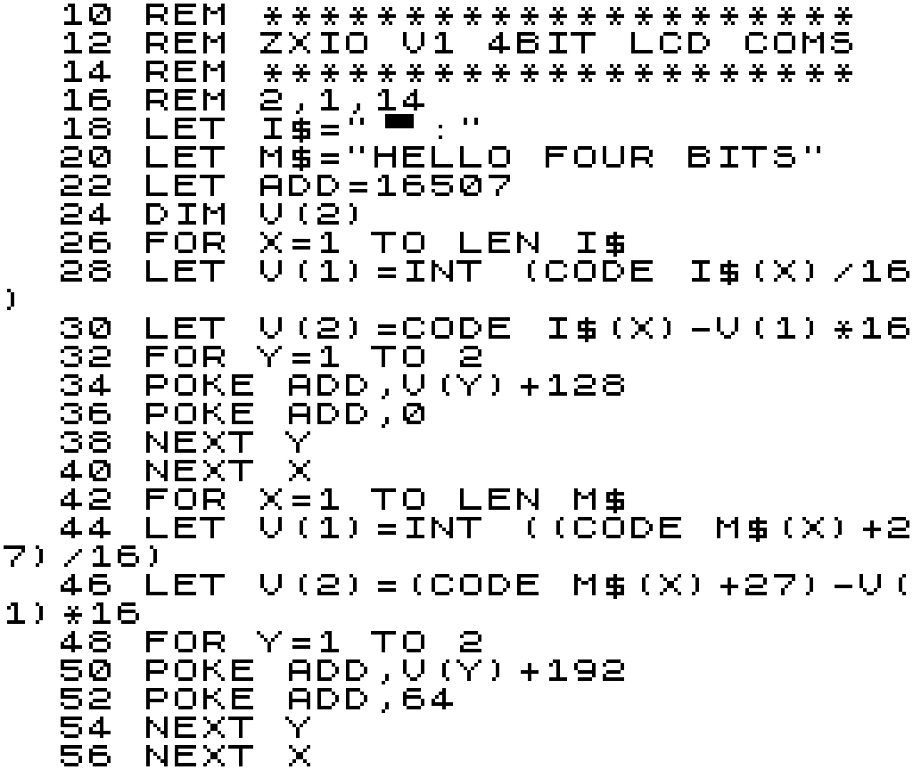 |
| ZX81 Code to drive LCD in 4bit Mode |
The program sends data to the LCD screen at a slow but satisfying speed. While this could be accelerated with code optimisation and pre-conversion of the ASCII text, I opted to maintain program similarity between the code directed at the V1 and V2 boards for a more effective side-by-side comparison (see next section).
 |
| Output from ZXIO V1 4Bit LCD Program |
Configuring for the ZXIO V2 Board
Setting up the V2 interface involves a process similar to that of the V1 version, with the added advantage of utilising the entire 8-bit input lines available on the HD44780 controller board. On the ZXIO V2 board, Port A pins 0 to 7 (facilitated by the 8255A chip) are mapped to the Data pins on the LCD. While, the Register Select and Enable lines are mapped to Port B pins 6 and 7, respectively.
 |
| ZXIO V2 to LCD Module |
As we're using the full 8-bit input, the configuration commands we need to send to the LCD interface vary slightly as we no longer need to put the device into 4-bit mode. (In both cases we're only using a very small subset of the available command set, just enough to get things moving along.)
HD44780 LCD Commands (Examples)
Code (HEX) | Code (DEC) | Command to LCD |
|---|---|---|
| 0x01 | 1 | Clear the display screen |
| 0x0e | 14 | Set Underline Cursor |
| 0x38 | 56 | Set to 8 Bit Mode, Configure Display |
To transmit data to the LCD interface using the V2 version, we must first configure Port A and Port B on the 8255A IC for output mode. This can be done by POKEing the control register at address 49151 with a value of 128. Once complete, we can begin transmitting control codes. The Enable line is set high via Port B pin (address 49149), while the control codes are transmitted through Port A (address 49148). After each code, the Enable lines is brought low.
As in the previous version, we first convert our message "HELLO EIGHT BITS" to ASCII before transmitting it to the LCD. We begin by setting the Enable and Register Select lines to high via Port B. Next, we send a character from our message string to Port A, and after transmission, set the Enable line back to low.
 |
| ZX81 Code to drive LCD in 8bit Mode |
Using the the ZXIO V2 board, our "HELLO" message is send somewhat more speedily, though still managing a rather 80s sci-fi future computer message output speed (All very MU-TH-UR 6000: Look out Ripply!).
Conclusions Drawn??
The discussion above only scratches the surface of the potential applications for both the V1 and V2 ZXIO boards. Despite its simplicity, the LCD test highlights the greater versatility of the V2 board in the long run. Nonetheless, this does not detract from the ease of use of the V1 board. With a simple address change to mend the issues outlined in previous blog posts, the V1 board is an ideal choice for a wide range of hardware experiments.
That being said, the ZXIO V2 design offers more possibilities for exploration due to the presence of the 8255A PIO chip. Future blog posts in this IO series will delve deeper into these possibilities.
Waiting for more in the IO series? Take a read of: Part 1, Part 2, Part 3, Part 4, Part 5 and Part 6.


0 comments:
Post a Comment