Showing posts with label ZX81. Show all posts

Saturday, August 22, 2026

Cronosoft Releases: Zevious 7 on Cassette

Leave a Comment


Zevious 7 Cassette Inlay

Out Now on Cassette: Zevious 7 Gets the Physical Cronosoft Treatment

The classic cassette format is getting another essential addition to its 16K library. Retro publishing house Cronosoft have officially released the physical tape edition of Zevious 7, bringing the impossible vertical shoot-'em-up to physical media.

Launch a Copy of Zevious

ZX81 Versions


Read More

Sunday, June 28, 2026

Zevious Seven: Getting a Bit More From the ZX81 Display

Leave a Comment

In the launch post, I briefly went over the making of Zevious Seven. In this follow-up, we'll take a slightly deeper look at how I put together a ZX81 shoot-'em-up, focusing on the acrobatics required to handle graphics, shadow files, and display file manipulation on a machine never built for action.


From "Box a Drop"to Writing a ZX81 Xevious-Like

There have been quite a number of modern and classic ZX81 games that push the expected boundaries of Sinclair's diminutive computer, but as far as I know (opinions and undiscovered facts may vary), there hadn't really been a true vertical SHMUP; one with a continuously scrolling background and uninterrupted game play. 

I'd been mucking around with the ZX81 DFILE and experimenting with shadow files earlier in 2026, to see how quickly you could update screens and flip between them, with the view to possibly making an at least a playable action game. I ended up with were some boxes scrolling onto the screen, and crashing into some water at the bottom. This happened at quite a respectable frame rate.

That got me wondering, wondering about Xevious. Why? Because. 

The Box Drop demo was basic, but combined with some experiences in writing ZX81 games, it did clue me in to exactly what was going to be required to make a scrolling game look fluid:

  • Compact Level Storage: A Optimised layout to compress vertical maps.
  • Graphics: Efficient handling of tile sets.
  • Speedy Display Updates: Rendering routines fast enough to handle ZX81 slowness. Like damn speedy.

Compact Level Storage: A level in a byte (a bit more that really)

Task one was to get a map, or at least the working idea for a map, up and running. For this, I wanted to be able to store a single line of map data into one byte. Or rather, a single byte should be able to store the minimum required to build a line of map data.

To achieve this, we'll be relying on two key things:
  1. The ZX81's screen dimensions.
  2. Run-Length Encoding (RLE).
The text-mode screen of the ZX81 is 32 characters wide. Storing a standard map linearly, where every single character on every single row gets its own byte, means a modest map of 256 rows would instantly devour 8KB of RAM. All rather expensive on a 16KB system.

However, a tile with a defined width of 4 characters combined with RLE, well, that's going to give us some possibilities.

The Maths of the 4-Character Tile

By making each background tile exactly 4 characters wide, a single horizontal screen row of 32 characters is comprised of exactly 8 tile slots (32 / 4 = 8). When we pair this with a 5/3 byte split, we can fit 32 unique tile types alongside a repeat counter of up to 8 total.

Bit:  7     6     5     4     3     2     1     0
   +-----+-----+-----+-----+-----+-----+-----+-----+
   |  V  |  V  |  V  |  V  |  V  |  V  |  V  |  V  |
   +-----+-----+-----+-----+-----+-----+-----+-----+
   \___________ 5 Bits __________/\____ 3 Bits ____/
                  |                       |
           High: 0–31 Tile          Low: 0–7 Repeat

That covers the background perfectly. But if we shrink the active play area by 4 characters to add a nice border around the playfield, it leaves an active play area 28 characters wide which only requires a maximum of 7 tiles to span a row.

As a background tile now never needs to repeat 8 times, we can completely repurpose that eighth repeat state (where the lower 3 bits equal 7) to act as an inline enemy spawn indicator. This frees up the top 5 bits to select from 31 distinct enemy types, spawning them at that exact position in the level map.

That now gets us down to a minimum of 1 byte per line.


Graphics: Tile Sets and Such

There are two tiles sets, one for the background an one for sprites. Background sprites are 4x3 with the Character / Enemy sprites set at 3x3.

The Background: Writing to the Shadow File

As the background tiles are 3 characters high, a new row of terrain data only needs to be processed once every 3 vertical scrolls, meaning we only read a single line from the map data.

Instead of writing directly to the active display, the game updates a shadow file area (33x23) reserved entirely for background data. The rest of the time, the engine simply shifts the existing buffer down within this shadow file, serving as a clean terrain master template. Each scroll cycle, we copy the bottom 19 rows from this shadow area to one of two D-FILEs.

The Sprites: Height Alignment and Visual Character

The choice of a 3x3 character grid for active elements provides us with a one-part technical solution and one-part artistic requirement. By making the moving sprites exactly three characters high, they align with the vertical dimension of the 4x3 landscape tiles, keeping map handling and coordinate tracking clean.

Fortuitously, this 3x3 footprint provides just enough definition to afford each element a unique appearance, while remaining small enough to not complicate handling or steal CPU cycles when tracking later.

The underlying sprite assets are actually stored as 3x6 blocks. Either the top three or bottom three lines are drawn depending on which specific D-FILE is being synced to at that moment, providing a brilliant built-in mechanism for generating character animations.

While the initial trigger to build and position a sprite is read directly from the compressed map data, the map itself does not store the full behavioural or visual definition of the entity. Instead, the map byte simply passes a selection index over to the main enemy or character structure. This tracking structure dictates an agent's real-time coordinate variables, firing states, and movement paths, ultimately determining exactly which specific 3x6 character template is extracted from the assets table to manifest that particular threat on screen.

Speedy Display Updates: Double-Buffering the D-FILE

The ZX81’s architecture leaves a painfully small window for game logic while rendering the TV signal. To maintain a fluid frame rate, the game engine abandons drawing and erasing characters within the main system-defined D-FILE.

Instead, a double-buffering strategy utilises two distinct D-FILEs. While one is actively viewed, the rendering loop composites the scrolling landscape from the map shadow file discussed earlier and the active 3x3 sprites into a hidden D-FILE. Once assembled, the engine swaps the active D-FILE pointer, timing the flip with the system variable FRAMES to instantly shift the background to the live display.

By focusing entirely on direct memory layout, custom shadow files, and raw pointer flipping, Zevious Seven achieves a continuous vertical scroll and animated sprites on hardware that was never built for real-time graphics. It's a testament to just how much performance you can squeeze out of a 16KB Sinclair machine when you stop fighting the architecture and start working with it.


Launch a Copy of Zevious

ZX81 Versions


Read More

Saturday, June 13, 2026

ZX81 Game: Zevious Seven

Leave a Comment
Zevious Seven

Bringing a touch of fast paced vertical scrolling arcade action to the ZX81: Not exactly renowned for its high speed action games, it's time to "write" some wrongs, punish some aliens, and prove the hardware doubters wrong by pushing the ZX81 to its 16K limits in the form of 'Zevious Seven'.


Defending Earth with the ZX81

The forces of Zevious have arrived: a sudden appearance of crop circles carved into the grasslands, the reactivation of ancient pyramids, and an overwhelming number of terrifying hostilities.

The United Earth Defence Force has appointed you to enact 'Plan Seven'. Piloting an advanced, uninsured fighter, you are humanity's last line of defence. Your (not at all) suicide mission: navigate occupied territory, outmanoeuvre Zevian forces, and break through to victory.

Zevious Seven in Game Screen
Zevious Seven: How long can you Defend Earth?

Playing the Game

Zevious is a pure SHMUP vertical arcade shooter. You must navigate a continuously scrolling landscape while managing incoming enemy fire and taking down alien targets.

To survive the onslaught, your ship is equipped with dual power cannons and high energy shielding. Taking hits from enemies or crashing into hostile craft will drain your power reserves, though your shields will slowly regenerate if you can manage to stay out of the line of fire long enough.

A word of warning: trigger discipline is essential! Your ship's cannons are prone to overheating. If you hold down the fire button for too long, your blasters will jam. You will need to release the trigger and let the systems cool before you can return fire, leaving you vulnerable to counterattacks.

The Alien Armada

The invaders deploy in complex attack waves, each requiring a different strategy to defeat or evade:
  • Airborne Threats: You will face sweeping Loopies, the heavily armed Loopy Bombers, diving Guppies, and the erratic, high-speed Zippers. You must also navigate through impenetrable flying Walls.
  • Ground Installations: Keep an eye on the terrain below. Destroying Radar stations, Launch Pads, and moving Tanks will significantly boost your score.

Controls

Zevious Seven offers full support for your preferred control method:
  • Keyboard: Default keys are 'Q' (Up), 'A' (Down), 'O' (Left), 'P' (Right), and 'M'' (Fire). If these don't suit your play style, press 'K' on the home screens to redefine your keyboard layout.
  • Joysticks: The game  supports Kempston, ZXpand, Sinclair (redfine your keyboard control) and Boldfield joystick interfaces for authentic, hot, arcade action.

Hardware Compatibility

  • System Requirements: A ZX81 with 16K of RAM or more is required.
  • Sound Support: Audio is supported via ZON-X and compatible interfaces.
  • Display Standards: This game is optimised for PAL systems. NTSC systems are fully supported, but please note that the action will run at a slower pace due to the refresh rate differences.
  • Expansion Hardware: Full support is included for the Tynemouth Software Minstrel 4th in ZX81 mode.
  • Emulation: For the best experience, the 'EightyOne' emulator is highly recommended.
Zevious Seven in Game Screen
Zevious Seven: Must knock out those pyramids.

A Little bit on the Making of Zevious Seven

Zevious is the kind of game I always thought should have been possible on a ZX81, yet somehow never got. After all, if the Apple II could have an official Xevious port, then the much more capable ZX81 really should have had its own clone. Well, now it does. Of course, creating a smooth, vertical scroller that fits into a mere 16K was a gruelling and slightly sanity-loosening experience.

A decent SHMUP demands a serious turn of speed. To hit those targets, the game employs double-buffering into multiple shadow DFILEs. This allowed for the loading of tiles directly into a pre-calculated shadow buffer, which is then alternated between DFILEs and layered with sprite data before being swapped into the active display. To prevent screen tearing, refreshes are strictly locked to the vertical frame rate. This is where we start noticing the difference between PAL and NTSC refresh rates; due to its unique architectural quirks, the PAL ZX81 is one of the few machines that actually operates faster in its native PAL mode.

There are two distinct tile sets: one for sprites and one for landscape elements. Landscapes are held in a 4x3 set; these are loaded every three cycles and scrolled down the screen every cycle. The sprites are managed in 3x6 sets, with half of each sprite being processed per cycle to handle the animations.

The fight between memory management and speed was a constant, uphill battle. Originally, all sprites and tiles were stored in a compressed format to save space, but this required too much processing power to keep the game running at an acceptable rate. While the concept tested well in isolation, once the surrounding game logic was implemented, the speed penalty became too much of an overhead. In the end, I opted to keep compression for the level data only.

The AY music and sound effects are functional, though admittedly on the basic side; space and timing constraints forced me to work within fairly tight limits. Sound effects are pre-configured, using a single-bit change for each effect, plus a further bit to re-trigger the AY chip on demand. The playback routine is similarly lean, we're not going to win any awards for sound design on this one!

Between these behind-the-scenes tricks and some tight collision detection, Zevious turned out surprisingly fast, at least by ZX81 standards.

Much thanks goes to Tynemouth Software, The Loud Scots Bloke and George Beckett for providing feedback, testing and ideas.

I’m very happy with how responsive it feels, and I hope you have as much fun defending the skies as I had building them!

Launch a Copy of Zevious

ZX81 Versions


Read More

Saturday, November 16, 2024

Dallas Time on the ZX81

Leave a Comment

A ZXIO Project: Intefacting with a DS12C887

Keeping track of the current date/time on a ZX81 serves no useful purpose in 2024, thus making it the perfect project for a ZX81, the perfect project for the ZXIO V2 interface cards and the perfect use of everybbodies favourite clock chip the Dallas DS12C887.


The Dallas Semiconductor DS12C887 RTC modules are well-known in retro computing circles for their integrated real-time clock and their gradually failing battery backup. However, they remain readily available, along with the core of the module the DS12885 which offers the same functionality only requiring an external battery backup. For simplicity's sake, and because I have some functional DS12C887 modules, this ZXIO project will use a complete module.


Configuration and Schematics

If you're unfamiliar with the ZXIO V2 or the 8255A I/O IC, be sure to check out the other articles in the ZXIO series on this site. In brief, the ZXIO V2 is an input/output card for the ZX81, built around the versatile 8255A IC. Notably, it's a memory-mapped device that allows its functions to be accessed from ZX81 BASIC.

Communicating with the DS12C887 RTC module is relatively straightforward. The general configuration, both in hardware and software, is:

  • Set up the ZXIO V2 / 8255A in Mode 0 for basic I/O.
  • Designate specific ports for communication with the RTC:
    • Port A: Data bus to exchange data with the RTC.
    • Port C: Control lines like chip select (CS),  read/write (R/W), Address Strobe (AS) and Data Strobe (DS).
The DS12C887 is set for Motorola timings, with the MOT pin connected to VCC. The Motorola mode seems to lend itself a little better to being interacted with. 

Interestingly, the Chip Select line on the RTC is active low, as is the Write signal on the R/W lines. I’ve chosen to invert these signals as this seems to make more sense when writing the BASIC program to control the clock. You'll notice on the schematic that I've used a CD74HC02 NOR gate to invert the signals.


As part of the Chip Select inversion, one input of the NOR gate is paired with another output from the CD74HC02, which is connected to ground. This setup creates a small delay, preventing the RTC’s memory from being cleared or reset during power cycles or resets, ensuring it retains its time and configuration data.


RTC for ZXIO V2 Circuit Schematic

A "Functional" Clock Program

Using the ZXIO V2 interface card, the ZX81 communicates with the RTC by sending and receiving signals through the I/O ports. Each I/O port, along with the Control Port, is memory-mapped to specific addresses on the ZX81. Port A corresponds to memory address 16380, Port B to 16381, Port C to 16382, and the Control Port to 16383. These addresses are used to send commands and data to the RTC. The time data stored in the RTC is in binary-coded decimal (BCD) format, and the program converts this data into a human-readable string for display on the ZX81.

The BASIC program to control all this is divided into two parts, or two separate programs, in reality. The "GET TIME" routine reads hours, minutes, and seconds from the RTC registers, formats them into a string, and displays the current time. The "SET TIME" routine, on the other hand, allows a new time to be programmed into the RTC by converting user-defined input into BCD and writing it back to the appropriate registers.

 
  10 REM **************
  15 REM ** GET TIME **
  20 REM ************** 
  25 LET Y=0
  30 LET A$=""
  35 LET T$=""
  40 FOR X=4 TO 0 STEP -2
  45 POKE 49151,128
  50 POKE 49150,130
  55 POKE 49148,X
  60 POKE 49151,144
  65 POKE 49150,132
  70 LET Y=PEEK 49148
  75 LET A$="0"+STR$ (10*INT (Y/16)+Y-INT (Y/16)*16)
  80 LET Y=LEN A$
  85 LET T$=T$+A$(Y-1 TO Y)+":"
  90 NEXT X
  95 PRINT AT 0,0;T$(1 TO 8)
 100 GOTO 170
 105 REM **************
 110 REM ** SET TIME **
 115 REM ************** 
 120 LET T$="225533"
 125 POKE 49151,128
 130 FOR X=0 TO LEN (T$)-1 STEP 2
 135 LET Y=VAL (T$(X+1 TO X+2))
 140 POKE 49150,130
 145 POKE 49148,LEN (T$)-X-2
 150 POKE 49150,133
 155 POKE 49148,Y-INT (Y/10)*10+INT (Y/10)*16
 160 PRINT Y-INT (Y/10)*10+INT (Y/10)*16,LEN (T$)-X-2
 165 NEXT X
 170 STOP
  

GET TIME (Lines 10–100)

his part retrieves the current time from the RTC module and formats it into a readable string.

  1. Initialisation:

    • Lines 25–35: Variables Y, A$, and T$ are initialised. T$ will hold the final formatted time.
  2. Reading Time Data:

    • Lines 40–90: A loop iterates through the time registers in reverse order (the RTC stores hours, minutes, and seconds in separate registers).
      • Line 45: Writes 128 to the control register to prepare the RTC for a read operation.
      • Line 50: Writes 130 to select the time register.
      • Line 55: Specifies which time register to read (X corresponds to seconds, minutes, or hours).
      • Line 60: Executes the read operation.
      • Line 70: Retrieves the register value using PEEK.
  3. Formatting:

    • Lines 75–85: Converts the binary-coded decimal (BCD) value from the RTC into a two-digit decimal number:
      • Y/16 extracts the tens digit.
      • Y-INT(Y/16)*16 extracts the units digit.
      • The digits are concatenated into A$ and appended to the time string T$ with a colon separator.
  4. Display:

    • Line 95: Displays the formatted time (first 8 characters) at the top-left corner of the ZX81 screen.
  5. Repeat:

    • Line 100: Ends the routine and jumps to the time-setting routine if implemented further.

SET TIME (Lines 105–170)

This part writes a new time into the RTC module.

  1. Initialisation:

    • Line 120: The variable T$ is hardcoded with a new time in the format HHMMSS (e.g., "225533" = 22:55:33).
  2. Writing Time Data:

    • Lines 130–165: A loop iterates through the string T$ in pairs of digits to set the hours, minutes, and seconds registers:
      • Line 135: Extracts two digits from T$ and converts them into an integer.
      • Line 140: Prepares the RTC for a write operation by setting the appropriate control values.
      • Line 145: Specifies the time register to write to.
      • Line 150: Converts the decimal value into BCD format and writes it to the RTC.
  3. Debugging/Confirmation:

    • Line 160: Displays the BCD-encoded value and the register being written to for verification.

Time Loop

With Line 100 changed to "GOTO 35," the "GET TIME" portion of the program becomes a continuously running clock—though it updates slightly slower than real time. The program, as written, takes just under 2 seconds to update. This could be sped up to some degree by only looping through the seconds and minutes as needed, rather than reading the entire time (hours, minutes, and seconds) every time. The video demonstration bellow is taken from slightly earlier version of the program and is slightly slower (slightly).


And that’s a wrap on reading and interacting with the Dallas Real-Time Clock—at least for now. We've successfully coaxed the ZX81 into telling the time (with a slight delay, of course). If we’ve learned anything, it’s that time waits for no one… except maybe for the ZX81, which could probably use a little more time to catch up.


Reference: Dallas RTC DS12C887 Module Pinout

Pin Name Description
1 MOT Motorola Timing Select. Connect to VCC for Motorola timings.
2 X1 Connections for Standard 32.768kHz Quartz Crystal – Internal.
3 X2 Connections for Standard 32.768kHz Quartz Crystal – Internal.
4 D0 Data Bus Line 0 (part of the 8-bit data bus).
5 D1 Data Bus Line 1 (part of the 8-bit data bus).
6 D2 Data Bus Line 2 (part of the 8-bit data bus).
7 D3 Data Bus Line 3 (part of the 8-bit data bus).
8 D4 Data Bus Line 4 (part of the 8-bit data bus).
9 D5 Data Bus Line 5 (part of the 8-bit data bus).
10 D6 Data Bus Line 6 (part of the 8-bit data bus).
11 D7 Data Bus Line 7 (part of the 8-bit data bus).
12 GND Ground.
13 CS~ Chip Select, active low. Selects the RTC for communication.
14 AS Address Strobe. Latches address bits on the falling edge.
15 R/W Read/Write input. Determines whether data is read from or written to the RTC.
16 GND Ground.
17 DS Data Strobe, active low. Enables reading or writing data to the RTC.
18 RESET Reset input, active low. Resets the RTC registers when asserted.
19 IRQ~ Interrupt Request, active low. Signals alarms or periodic events.
20 VBAT Connection for a Primary Battery – Internal.
21 RCLR~ Active-Low RAM Clear. Pin is internally pulled up.
22 NC No Connection (not used).
23 SQW Square Wave output. Outputs a programmable frequency or 1 Hz for timekeeping.
24 VCC Power supply input (typically +5V).


Read More

Tuesday, June 25, 2024

ZXIO V2 Experimenters Kit Out Now

Leave a Comment


ZXIO V2 IO 8255A Experimenters Kit Parts

After working extensively on the ZXIO Blog series, I aimed to create a memory-mapped I/O board ideal for experimenting with ZX BASIC, as the ZX81 lacks the ability to use IRQ-mapped devices without resorting to machine code routines. The end result is the ZXIO V2, which is based on the use of an 8255A Programmable Peripheral Interface IC. 


Apparently, I wasn't the only one wishing for such a device. The blog series was extremely popular, and the demand for an easy-to-use I/O board for the ZX81 was high. After additional development and testing, I'm finally releasing the kit.


ZXIO V2 IO 8255A Experimenters Kit Complete
A Built ZX81 ZXIO V2 Experimenters Kit

What's in the Kit?

  • ZXIO V2 PCB and parts: The main component of the kit and brains of the operation.
  • ZX BUS Expander PCB and parts: A ZX81 BUS extension card, the ZXIO or other cards of similar design can be attached to this board.
  • ZX IO LED Board and parts: A unique expansion board designed to be mounted directly to the ZXIO V2 expansion headers. 
  • ZXIO Breakout Board and parts: Designed to be used in conjunction with a breadboard for experimentation and prototyping. (Breadboard not included). 
  • IDC ribbon Cable.
The kits contain everything needed to build the base ZXIO V2 board, including an LED board and a breakout board. All parts are brand new, with the exception of the 8255A IC, which is a reclaimed component. This decision was made to manage costs effectively; sourcing new versions of this IC would significantly increase the kit price, potentially doubling it.

Support and Future Projects

As with the ZX-Key Keyboard before, the ZXIO V2 has a dedicated support page where updates and detailed information about the device will be posted. This page will include comprehensive build instructions, troubleshooting tips, and other relevant details to assist users in assembling and using their kits.

After the initial release, I'm planning additional posts and new projects centred around the ZXIO V2 and its usage.

Where to get a Kit?

Kits will be available at Sell My Retro, at the time of writing priced at $98 USD plus shipping.

Hope all will enjoy building abd experimenting with this ZX81 kit, and I'd love to hear about experiments and / or even host some ideas on this site. Enjoy.


Read More

Saturday, May 25, 2024

Cronosoft Releases: Minoss Knossoss for the ZX81 on Tape

Leave a Comment

Cronosoft has announced the release of Minoss Knossoss for the ZX81 on Tape. You can now dive deep into the legendary labyrinth and embark on an unforgettable adventure that brings the rich mythology of ancient Minoan Crete to life on your ZX81.


ZX81 Game: Minoss Knossoss Tape Cover Art
Minoss Knossoss the ZX81 game Released on Tape by Cronosoft 

For any great release you need exceptional cover art: I produced the base artwork for the cover of the physical release, featuring a menacing Minotaur alluding to the horrors that await the adventurous archaeologist. With Simon of Cronosoft completing the stunning package design and putting the game through rigorous testing on real hardware, ensuring smooth loading from the tapes.


So now there's no excuse not to experience the thrill of the labyrinth and the beauty of retro gaming with Minoss Knossoss on your ZX81. Stay tuned for the official release date and prepare for an epic journey! 


Uncover a Copy of Minoss Knossoss


ZX81 Version


Read More

Monday, April 08, 2024

ZX81 Game: Minoss Knossoss

Leave a Comment

ZX81 Game Minoss Knossoss, Screen shot  of Minoss Knossoss Title / attract screen

Having had Tut-Tut successfully ported to numerous 8-bit systems, it feels fitting to elevate the gaming experience by launching a sequel to the original tomb-raiding puzzle adventure in the form of 'Minoss Knossoss'.


Minoan Archaeology with the ZX81

Life on the ancient history speaking circuit had grown dull. Tired of recounting your successes at the tombs of Tut-Tut, you yearned for the exciting life of a practical archaeologist. Now, in 1924, after a month's journey by tramp steamers, you arrived in Crete at the Palace of Knossos.


Initially finding little, concrete leads began emerging from your excavations, presenting opportunities too good to pass up. Ancient tales of curses and the fabled Minotaur, along with the legendary workshops of Daedalus, beckon to the grand adventurer.


Here in Crete, where the labyrinth of the Minotaur lies, with mysteries and dangers aplenty, you'll cement your reputation as the greatest archaeologist of all time, or die trying.


ZX81 Game Minoss Knossoss, Screen shot of level 1 "kephala Naos"
Can you find your way into the labyrinths beneath Knossos?

Playing the Game

Minoss Knossoss is one part puzzle, two parts arcade action. The game comprises 20 levels, with the final level being the hidden workshops of the mythical craftsman Daedalus; accessible only to those who have mastered the labyrinths (accumulated 2500 points).


Collect gems, amulets, bracelets, keys, and hourglasses to earn points. Amulets freeze the player, while bracelets halt creatures. Hourglasses award you extra time to complete a level. Completing a level requires the player to collect keys, open doors, and move blocks before finding exits to lower labyrinthine levels, all while keeping an eye out for King Minos's mythical guardians.


Labyrinth Guardians

Strategically utilise hidden crevices to evade enemies, capitalising on the predatory instincts of Harpies and Minotaurs to distract them while you unravel the puzzles.

  • Serpents: Massive snakes roam the levels. They are timid, and while they won't actively hunt you down, be cautious—cornering them may provoke a strike.
  • Harpies: With the body of a bird and the visage of a human, these winged creatures embody an avian ferocity and supernatural penchant for vengeance.
  • Minotaurs: Renowned as the ultimate terror within the labyrinth, these formidable creatures relentlessly pursue their prey, turning the maze into a deadly game of survival.

Controls

  • Keys: ‘O’ left, ‘P’ right, ‘Q’ up, ‘A’ down, 'F' to pause and ‘R’ to reset the level (at a cost).
  • Joystick / Gamepad: A Kempston standard Joystick addaptor is supported.

Sound

  • AY Sound is supported via ZON-X sound cards and compatibles such as the ZXPand+


The Making of Minoss Knossoss

Minoss Knossoss stands as the direct sequel to Tut-Tut, a game I originally crafted for Paleotronic Magazine and the Sinclair ZX Spectrum. Following its initial release, Tut-Tut underwent widespread porting to various 8-bit platforms by a diverse array of developers. Notable among them are Dave Curran for the PET, myself and Dave for the Vic20, Sheila Dixon's adaptations for the RC2014 and MSX machines, and George Beckett's rendition for the Jupiter Ace.


Having played a role in each iteration of Tut-Tut's porting process, we seized the opportunity to introduce numerous enhancements with each development cycle. However, there inevitably comes a point where further improvements reach a natural limit, paving the way for a full-fledged sequel.


ZX81 Game Minoss Knossoss,  Screen shot of level  "Teucers Bow"
Deeper into the Labyrinth, Level Teucers Bow

In essence, the gameplay of Minoss Knossoss will feel familiar to fans of its predecessor. However, the sequel introduces additional monster types, including Serpents, Harpies (with movement similar to the mummies from Tut-Tut), and, of course, Minotaurs, each contributing an extra layer of challenge. And what would be the point of new monster types without the ability to have more of them on screen at one time? Furthermore, players will encounter a new item type in the form of hourglasses, which provide valuable extra time to navigate through certain levels.


Among the less conspicuous enhancements are newfound abilities to strategically trap monsters, sparing players from potentially frustrating level restarts. Also note that, players can now enjoy the long-awaited feature of pausing the game, particularly notable feature for ZX81 users. Additionally, the playing area has been expanded, offering a more immersive gaming experience.


Behind the scenes, I've implemented enhancements to optimize how levels are stored, Refined game timing to synchronize directly with the clock cycles of the ZX81/Z80, resulting in smoother gameplay. And, of course, I've finally integrated joystick support and rudimentary sound for those fortunate enough to be using ZON-X sound cards and Kempston Joystick adapters (or emulators).


Regrettably, the one feature omitted is the level code input option, allowing players to skip completed levels. Unfortunately, due to space constraints, this feature couldn't be included. However, rest assured that it will make a comeback in future ports for other 8-bit machines—just a hint of things to come.


With all of these features and more, I hope you enjoy Minoss Knossoss.


Uncover a Copy of Minoss Knossoss


ZX81 Version


Read More

Sunday, January 07, 2024

ZXIO Interface for the ZX81: Part 6

Leave a Comment


ZX81 ZXIO TalkBot interface and ZXIO Interface
ZXIO-TalkBot and ZXIO V2 (with minor revisions)

ZXIO-TalkBot

Alright, we've got our reliable ZX81 all decked out with the ZXIO V2. Now, let's kick things up a notch - how about introducing an SP0256 (the original retro) speech chip to the party? This little marvel can transform pre-defined sounds (allophones) into speech, bringing a whole new layer of excitement to our setup.


Prior to designing the Talkbot, I made a slight modification to the ZXIO V2 (now V2.1 I guess) board. I introduced a new 4-pin header on the left side of the board, incorporating the NMI, Reset and Clock (foreshadowing)  signals from the ZX81, along with a Gnd line. This addition was made with the anticipation that the extra signals would be beneficial for future expansions. Moreover, the header enhances stability when connecting more extended expansion cards directly to the front of the ZXIO interface.


Of course it's well worth noting that it's quite possible to build an entirely separate / standalone interface board for the SP0256-AL2. When designing the ZXIO-Talkbot, I consulted a number of designs as a reference before planning the ZXIO plugin card. I highly recommend 'How to Make Your Computer Talk' by Steven J. Veltri as an excellent starting point. His book covers interfaces for a number of 80s home computers including the ZX81, along side in depth details on how the SP0256-AL2 itself works.


How to Make Your Computer Talk: T/S 1000, ZX80, and ZX81 Speech Circuit Schematic

The interface circuit from 'How to Make Your Computer Talk' is depicted above. Although as it's designed for Machine Code programs, it is not accessible to BASIC due to the absence of Memory Mapping. However, the fundamental design can be readily adapted for use with the ZXIO expansion card.


In the ZXIO-Talkbot, all addressing and data lines are interconnected with the 8255A on the ZXIO V2 interface card. Consequently, their control is handled in a manner similar to the earlier experiments where we employed the ZXIO V2 to manage an HD44780 LCD board. 


Unlike the 'How to Make Your Computer Talk' board, the clock signal is not produced by a separate 3.12MHz crystal; instead, we utilise the ZX81's own oscillator, which operates at 3.25 MHz—sufficiently close. Additionally, a separate RESET signal is not required; this line is directly connected to the ZX81's RESET. While, in future versions, it could be managed by the 8255A, such a configuration might be considered overkill.


ZXIO TalkBot Schematic, Featuring the SP0256-AL2 Speech Chip


The only other notable difference is the removal of the op-amp. Instead, I've provisioned a 3.5mm headphone jack that's easy enough to connect to powered speakers for all your amplification needs. (Note that there is also a direct connector that goes to my ZonZX-81 sound card.)


Talking the TalkBot

The SP0256 is a speech synthesis chip designed to convert phonetic information into audible speech. It operates by receiving allophone codes, which represent specific variants of a phoneme occurring in particular linguistic contexts. Allophones, unlike phonemes, are concrete variations of sound within a language.


In short, this means that you can't simply give the TalkBot a word and have it 'say' it correctly. Instead, you need to supply it with an allophone list that will hopefully construct a word from its sound samples. Below is a list of allophones, their sound descriptions, and suggested timings that each should be allowed to run.


Unfortunately, the timings are not so useful in ZX81 BASIC, as the instructions take more time to process than desired. Feeding the Talkbot the allophones and ignoring time signatures works sufficiently well. Of course, there's nothing stopping us from addressing the Talkbot/SP0256 later in Assembly for a little more accuracy.


ZXIO SP0256-AL2 Allophones Reference for the ZX81
SP0256-AL2 Allophones Reference

To transmit data to the ZXIO-TalkBot interface we must first configure Port A and Port B on the 8255A IC for output mode. This can be done by POKEing the control register at address 49151 with a value of 128. Once complete, we can begin transmitting control codes. 


The Enable line is first set low on Port B at address 49149, 0, while the allophone control codes are transmitted through Port A at address 49148, 'code'. Then Enable line 1 on port B is set high at 49149, 1. After that, the Enable line is brought low again.


ZXIO-TalkBot and ZXIO V2 interface cards (plus ZX Minstel ZXpand & ZonZX-81)


LCD and TalkBot

The fun doesn't end there; after all, the ZXIO is designed to allow multiple interfaces to be attached simultaneously. As such, we can reuse the LCD interface from the previous project in Part 5, and have it write out what we're asking the ZXIO-TalkBot to say at the same time. For this, we only need to use the upper bits at address 49149 (Port B) to enable and disable its control lines.


ZX81 ZXIO V2 running the LCD and ZXIO-TalkBot Togther Demo 


For your complete audio-visual enjoyment, please play the video below to witness and hear the results. This is just a sample of what could be achieved; the ZXIO V2 Cards and expansions offer almost limitless possibilities. For instance, they could be employed to power a wide array of applications, even extending to interfacing with devices like an Arduino. The potential is expansive, and the video provides just a glimpse of the creative possibilities.


For the moment, that pretty much concludes this mini-series on the ZXIO and ZXIO V2 expansion cards. Further projects based on the board are in the pipeline, and if there's enough interest, I may decide to produce kits and/or complete units. Please let me know if you'd be interested in obtaining a board. If you haven't already, please read over all the related earlier (and future) articles listed below.


See all the other entries for this project:   Part 1, Part 2, Part 3, Part 4, Part 5 and Part 6.


Read More

Sunday, May 07, 2023

ZXIO Interface for the ZX81: Part 5

Leave a Comment

IO Boards Comparison, Featuring Hitachi LCDs

Now that we have 2 differing IO boards, why not put them in a side by side comparison. I figured a good test of the board would involve a simple communications project, such as writing out to a character based HD44780 compatible LCD screen.


An HD44780 LCD panel is a character-based liquid crystal display that can display 16 characters per line and up to 2 lines of text. It is widely used in embedded systems and DIY projects because of its low cost, low power consumption, and ease of use. The HD44780 LCD panel is compatible with a wide range of microcontrollers and can be interfaced using a 4-bit or 8-bit command set. We really couldn't ask for a more amiable device for testing ZXIO board differences with.


HD44780 LCD Module Pin out 
Pin
Signal
Function
1VSSGround
2VCC+5 Volts
3VEEContrast adjustment 0V: High Contrast
4RSRegister Select 0: Command, 1:  Data
5R/WRead/Write 0: Write, 1: Read
6ENEnable. Falling edge triggered
7DB0Data Bit 0 (Not used in 4-bit Mode)
8DB1Data Bit 1 (Not used in 4-bit Mode)
9DB2Data Bit 2 (Not used in 4-bit Mode)
10DB3Data Bit 2 (Not used in 4-bit Mode)
11DB4Data Bit 4
12DB5Data Bit 5
13DB6Data Bit 6
14DB7Data Bit 7
15LED A+Anode Back light +  
16LED K-Cathode Back light -

Configuring for the ZXIO V1 Board

Connecting the LCD module to the ZXIO is a straightforward process. The output pins O0 to O3 of ZXIO should be paired with DB4 to DB7 on the LCD board to send data from ZX81 to the module. In addition, the output line 6 of ZXIO must be linked to Register Select, while the output line 7 should be connected to the Enable Pin.

The lines responsible for controlling the power to the LCD module and screen contrast are as follows: VSS is linked to the ground, VCC is linked to +5 volts, and VEE is connected to the ground through a variable resistor (across the +5v line). To adjust the screen brightness, connect the LED+ pin to +5 volts and the LED-pin to the ground through a 220 ohm resistor (resistor is optional as some of these Module clones have the required resistor built in).


ZXIO V1 to LCD Module
That's the hardware out of the way, the rest is all down to some BASIC programming on the ZX81 targeting the ZXIO and LCD display module.

HD44780 LCD Commands (Examples)
Code (HEX)
Code (DEC)
Command to LCD
0x011Clear the display screen
0x022Set to 4 Bit Mode
0x0e14Set Underline Cursor
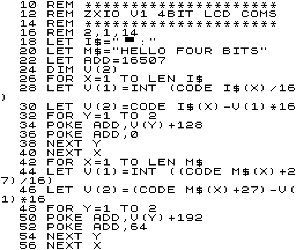
The below program connects the HD44780 to the ZX81 / ZXIO V1 at address 16507. It initializes the HD44780 by sending a sequence of control codes to set the display mode, enable the display, clear the display, and set the cursor to the home position. To send each byte, it needs to be split into 2 * 4 bits and sent consecutively. The Enable line must be brought high and then low to signal each 4 bit segment sent.

Subsequently, the program transmits the message "HELLO FOUR BITS" to the HD44780 by encoding each character as its corresponding ASCII code. To achieve this, the ZX81 Characters  should to be converted to their ASCII counterparts. As previously mentioned, each byte is then split into two 4-bit segments, with both the Enable and Register Select lines being set high. After transmitting each 4-bit segment, the Enable line is set low once again.

ZX81 Code to drive LCD in 4bit Mode

The program sends data to the LCD screen at a slow but satisfying speed. While this could be accelerated with code optimisation and pre-conversion of the ASCII text, I opted to maintain program similarity between the code directed at the V1 and V2 boards for a more effective side-by-side comparison (see next section).

Output from ZXIO V1 4Bit LCD Program

Configuring for the ZXIO V2 Board

Setting up the V2 interface involves a process similar to that of the V1 version, with the added advantage of utilising the entire 8-bit input lines available on the HD44780 controller board. On the ZXIO V2 board, Port A pins 0 to 7 (facilitated by the 8255A chip) are mapped to the Data pins on the LCD. While, the Register Select and Enable lines are mapped to Port B pins 6 and 7, respectively.

ZXIO V2 to LCD Module

As we're using the full 8-bit input, the configuration commands we need to send to the LCD interface vary slightly as we no longer need to put the device into 4-bit mode. (In both cases we're only using a very small subset of the available command set, just enough to get things moving along.) 


HD44780 LCD Commands (Examples)
Code (HEX)
Code (DEC)
Command to LCD
0x011Clear the display screen
0x0e14Set Underline Cursor
0x3856Set to 8 Bit Mode, Configure Display
To transmit data to the LCD interface using the V2 version, we must first configure Port A and Port B on the 8255A IC for output mode. This can be done by POKEing the control register at address 49151 with a value of 128. Once complete, we can begin transmitting control codes. The Enable line is set high via Port B pin (address 49149), while the control codes are transmitted through Port A (address 49148). After each code, the Enable lines is brought low.

As in the previous version, we first convert our message "HELLO EIGHT BITS" to ASCII before transmitting it to the LCD. We begin by setting the Enable and Register Select lines to high via Port B. Next, we send a character from our message string to Port A, and after transmission, set the Enable line back to low.

ZX81 Code to drive LCD in 8bit Mode

Using the the ZXIO V2 board, our "HELLO" message is send somewhat more speedily, though still managing a rather 80s sci-fi future computer message output speed (All very MU-TH-UR 6000: Look out Ripply!).

Conclusions Drawn??

The discussion above only scratches the surface of the potential applications for both the V1 and V2 ZXIO boards. Despite its simplicity, the LCD test highlights the greater versatility of the V2 board in the long run. Nonetheless, this does not detract from the ease of use of the V1 board. With a simple address change to mend the issues outlined in previous blog posts, the V1 board is an ideal choice for a wide range of hardware experiments.

That being said, the ZXIO V2 design offers more possibilities for exploration due to the presence of the 8255A PIO chip. Future blog posts in this IO series will delve deeper into these possibilities.

Waiting for more in the IO series? Take a read of:  Part 1, Part 2, Part 3, Part 4, Part 5 and Part 6.


Read More

Sunday, April 16, 2023

ZXIO Interface for the ZX81: Part 4

Leave a Comment


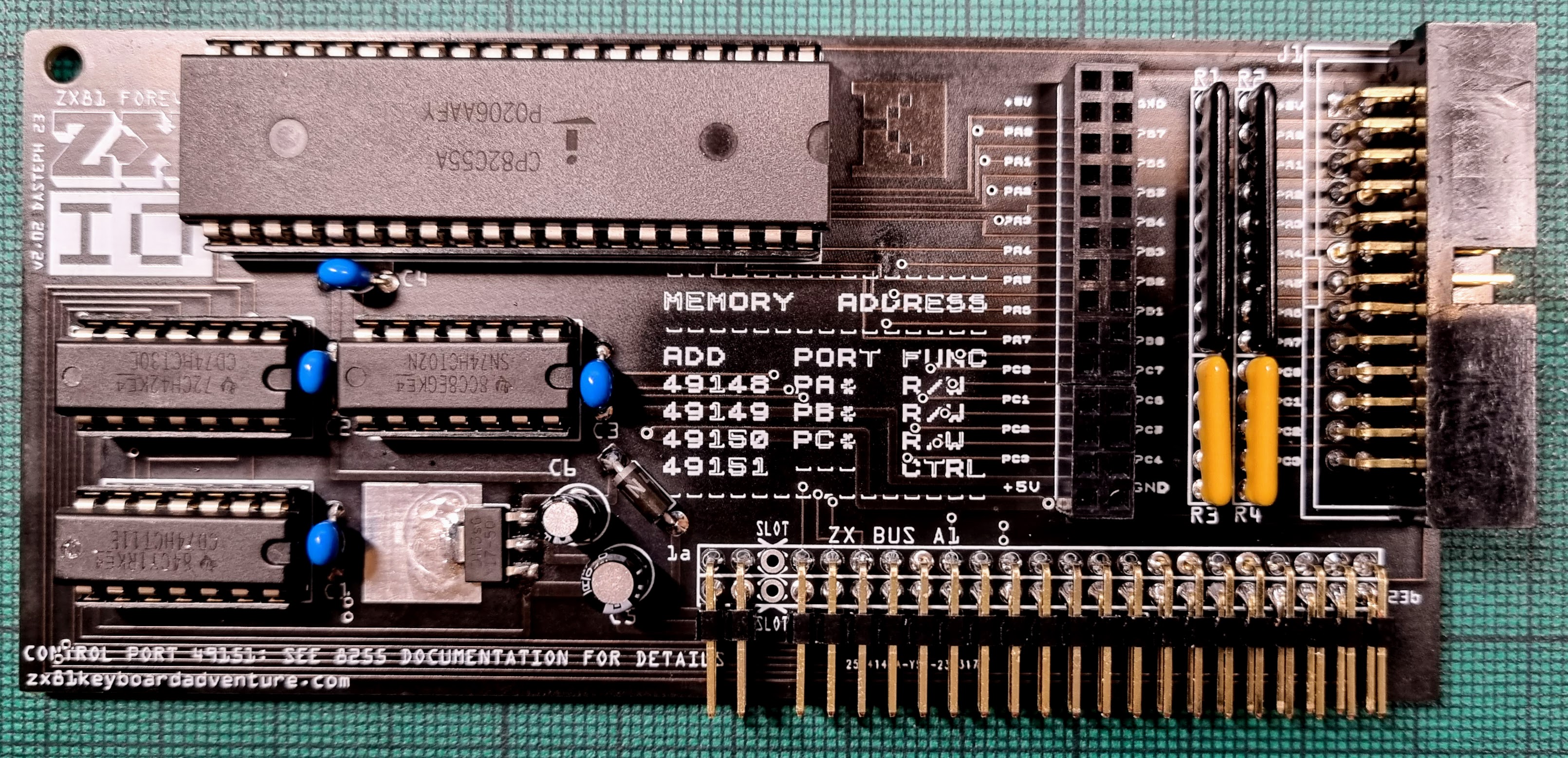
ZX81 ZXIO V2 Input Output Card with LCD Shield
ZXIO V2 Card with LED Expansion Board

Previously I built a simple Input / Output board for the ZX81, tested it, identified some self induced errors then hinted that it may be worth changing designs completely. Way back in Part 1 I'd already come to the conclusion that I really shouldn't make this a simple project, so of course I went back and stared things again.

Why Change  Now?

Didn't the last design work and only really require some minor addressing changes? Yes, and that would be a perfectly fine end to the IO project. Still I wished to take this further and build a more capable board. Note that the overall aim of building a relatively simple interface is still a primary goal.


The IO version One card has a minor limitation in that it can only support an 8-bit wide addressing, which may not be sufficient for more complex hardware that requires access to at least a partial 16-bit width address space to access control lines while still being able to send and receive 8 bits. There are several ways to address this issue, such as using 4-bit modes or using 7 bits for data and the remaining bit as a control line. However, the feasibility of these solutions depends on the specific interface requirements of the project.


One possible solution is to double the IO options by adding an extra set of latch and buffer ICs. However, this would increase the complexity of building the board, including routing and address decoding. Other options could involve employing a "standard" IO IC.


The 8255A, the IO Chip of Choice (This Time)

Three suitable IO ICs come to mind for our purposes: the Z80-PIO (Parallel Input/Output Interface), the 8255A-PPI (Programmable Peripheral Interface) and the W65C22N-VIA (Versatile Interface Adaptor). All three of these chips are period correct for the ZX81, in production and available of the shelf today (at least in 2023).


For Version 2 of the IO board I selected the 8255A, as it's pretty well documented, and as a bonus it made an appearance in a ZX81 IO board designed by A. Daykin for Maplin's 'Project Book 04' from 1983. With some modifications to the Addressing and IO configurations to make it more suitable for experimentation, the Maplin board can be made pretty well perfect for our needs.


Period Inspiration from Maplin Project Book 04 - 1983
The 8255A IC is a chip that serves as a programmable peripheral interface, allowing for parallel input and output. It has three ports: Port A, Port B, and Port C. Each port can be configured as either an input or an output. Port C can be split into upper and lower blocks, each with the option to be programmed as an input or output. The IC also has a control register that is used to set the mode of operation for each port. With these features, the 8255 IC can replicate and even expand upon all the functions that the first version of the ZXIO board was capable of achieving. It can actually do fair bit more, but we may explore that latter on in this series of posts. 

Maplin IN 

The Maplins design is appropriately simple, making it easy to connect the 8255A to the ZX81. Note that 4 contiguous address locations require mapping, this performed partly by the 8255A and then the supporting ICs. The 8255A chip has two address lines on pins 8 and 9, which are directly linked to the ZX81 address lines Al and AO. The 74 series ICs then handle the remaining address decoding, and enabling of the 8255A when pin 6 is set to logic level 0. All data lines from the ZX81 are directly connected to the 8255A, along with write and read signals. The reset line on the 8255A at pin 36 is tied to GND.


The 16 IO pins of the 8255A that make up Ports A and C are directly connected to pin headers at the edge of the Maplin board for external device connection. However, the pins of Port B are linked to IC5 and IC6, which buffer the outputs from the 8255A. In conjunction with a set of 4.7k resistors, this setup offers protection against overload. The purpose of this configuration is to drive potentially higher voltage equipment from Port B. A side affect of the buffering is to limit Port B to output only.


Each IO Port and a Control Port are Memory Address Decoded back to the ZX81, Specifically, Port A corresponds to memory address 16380, Port B corresponds to memory address 16381, Port C corresponds to memory address 16382, and the Control Port corresponds to memory address 16383. These addresses are located at the top of ZX81s 8 to 16k range where a copy of the ROM would normally be shadow mapped. Refer back to Part 2 in this series for details on address ranges and suggested uses.


** For additional details on the Maplin Board I'd recommend Allan Faulds blog page, where he builds up an original Maplin IO Board purchased in the 1980's. **


ZXIO V2 OUT

Although there aren't many modifications needed to transform the Maplin into a ZXIO V2, there are a few adjustments I would like to implement to enhance the design's practicality for contemporary experimentation.


The initial modification I made was to adjust the address mapping to span from 49148 to 49151. This will position the device at the upper end of the 40-48k memory segment, beyond the reach of numerous contemporary and historic memory expansion cards (not all, but many). 


I eliminated the buffering ICs from Port B, if buffering becomes necessary, we can always incorporate that back into external hardware. I also took the opportunity to ground output lines on Ports A to C via 4.7k resistors, this will prevent floating values on the lines when they're not connected to anything. Additionally the Reset line on the 8255A is now tied to the Z80 / ZX81's reset signal, inverted through spare NAND gates from the address decoding ICs.


ZXIO V2 Schematic.

The last functional modification consists of two headers. The first one is an IDC header resembling the ZXIO version 1 board, which includes the IO Lines, Ports A to C, Ground, and +5 Volts. This facilitates the use of IDC cables to connect to external breadboards or built-up external devices. Additionally, I added a female header in parallel, allowing for direct connection to plug-in boards, like the LED "hat" shown in the photo at the top of this post.


ZXIO V2 Test Board

Next Post?

This should mostly cover the essential hardware details of ZXIO V2. In my next blog entry, I plan to conduct a quick comparison between the old and new ZXIO boards. Although I am confident that V2 is a more versatile board, V1 remains a decent option for basic experimentation. Lets see, stay tuned for the next post.

Until then see all the other entries for this project:   Part 1, Part 2, Part 3, Part 4, Part 5 and Part 6.


Read More